Heddle, especially lifting heddle

a lifting heddle and heddle technology, applied in the field of heddles, can solve the problems of difficult manipulation of m2 screws, inability to utilize screws larger than m2, and affect the travel of warp yarn along the heddle, so as to achieve the effect of being ready to secur

Active Publication Date: 2007-03-06
GEBR KLOCKER
View PDF7 Cites 12 Cited by
  • Summary
  • Abstract
  • Description
  • Claims
  • Application Information

AI Technical Summary

Benefits of technology

[0009]It is the object of the invention to form a heddle of the type mentioned herein above in such a manner that it can be readily secured to the heddle frame or a heddle ridge bar by means of captive parts and by toolless mounting.
[0010]In accordance with the invention, this object is solved by having the head portion and / or the base portion adapted to be interlockingly, more specifically non-slidably, fixed to the heddle frame or to the heddle ridge bar by means of a detent system. Accordingly, the heddle, more specifically the lifting heddle, is snap-fitted onto the heddle ridge bar. Mounting is much easier this way than if small screws are to be cumbersomely inserted and screwed into small openings whereby it is further possible that access be restricted during mounting.
[0012]There is more specifically provided that the eyelet of the head portion and / or of the base portion of the heddle corresponds approximately to the cross section of the heddle frame or of the heddle ridge bar, with the detent system including a detent lug or knob that is directed toward the heddle frame or of the heddle ridge bar and is adapted for insertion into a mating detent opening of the heddle frame or of the heddle ridge bar. Heddles, and more specifically lifting heddles, are substantially made from a plastic material. Such plastic materials have a certain inherent elasticity so that the detent lug is pressed into the mating opening in the heddle frame or in the heddle ridge bar in the region of its head portion or of its base portion by the very inherent elasticity of the plastic material. In order to prevent the detent lug from inadvertently slipping out of the detent opening as a result of the vibrations occurring during operation of the weaving machine, there is provided, according to another feature, that a resilient tongue be disposed in the wall of the eyelet facing the detent lug, said tongue pushing the detent lug into, or pulling it out of, the detent opening, that is to say that the tongue projects into the eyelet when not mounted to the heddle ridge bar.
[0013]According to another feature, the head portion and / or the base portion comprises a magnet located behind the knob or the detent lug. Accordingly, the magnet is in the immediate neighborhood of the heddle ridge bar or of the heddle frame. The heddle ridge bar in particular is made from metal so that, thanks to the magnetic force it exerts onto the heddle ridge bar, the magnet prevents the knob or the detent lug from slipping out of the detent opening. This means that the detent lug is pulled into the detent opening by the magnetic force.

Problems solved by technology

If the end of the heddle ridge bar projects beyond the width of the heddle, this would impair the travel of the warp yarn along the heddle.
Screws larger than M2 cannot be utilized since the size of the head portion or the base of the heddle forbids the use of larger screws.
Manipulation of an M2 screw is very complicated as such a screw gets easily lost and is also very difficult to manipulate by hands.

Method used


Image

  • Heddle, especially lifting heddle
  • Heddle, especially lifting heddle

Examples


Embodiment Construction

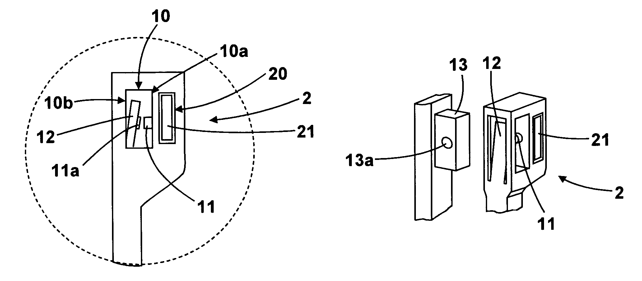
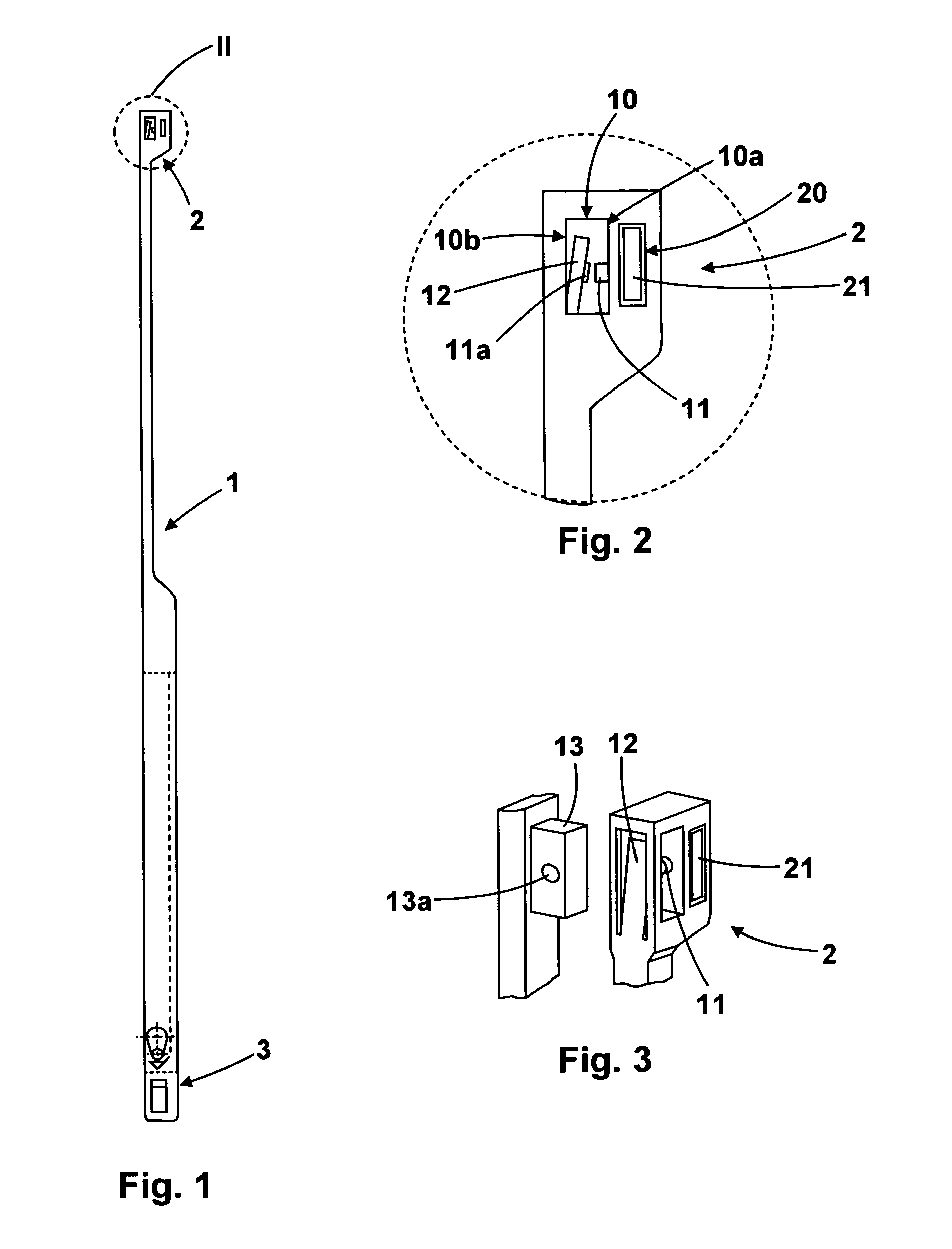
[0019]The heddle, which is indicated generally at 1, comprises a head portion 2 and a base portion 3. The base portion 2 possesses an eyelet labeled at 10 in the form of a slot or an opening. The latter needs not be closed at the top, as one would expect an “eyelet” to be. Inasmuch, it may be an open eyelet. In the mounted state of the lifting heddle, the eyelet 10 has two vertical walls 10a and 10b, a knob 11 being provided on, and associated with, the wall 10a of the eyelet 10. In the region of the wall 10b of the eyelet 10 there is the resilient tongue 12. The resilient tongue 12 causes the detent lug or the knob 11 to be pushed or pulled into the detent opening 13a of the heddle ridge bar 13 (FIG. 3). The resilient tongue 12 itself advantageously also comprises a detent lug or knob 11a, with the heddle ridge bar being taken hold of in a tongs-like fashion. If the detent opening 13a in the heddle ridge bar 13 is a through hole, the two detent lugs 11, 11a engage this detent openi...


PUM


Abstract

The subject matter of the invention is a heddle (1), more specifically a lifting heddle as part of a leno selvedge device, the heddle comprising a head portion and a base portion with a closed or an open eyelet for mounting to a heddle frame or to a heddle ridge bar (13), the head portion and / or base portion (2, 3) being adapted to be secured stationarily to the heddle frame or the heddle ridge bar (13), with the head portion (2) and / or the base portion (3) being adapted to be interlockingly and non-slidably fixed to the heddle frame or to the heddle ridge bar (13) by means of a detent system (11, 12, 13a).

Description

CROSS-REFERENCE TO RELATED APPLICATIONS[0001]This application claims Priority from German Application No. DE 10 2004 030 913.2-26 filed on 25. Jun. 2004BACKGROUND OF THE INVENTION[0002]1. Field of the Invention[0003]The present invention relates to a heddle, especially to a lifting heddle as a part of a leno selvedge device, said heddle comprising a head portion and a base portion with a closed or an open eyelet for mounting to a heddle frame or to a heddle ridge bar, said head portion and / or base portion being adapted to be secured stationarily to the heddle frame or the heddle ridge bar. As used herein, the term “open eyelet” is to be construed as a slot for example.[0004]2. Description of the Prior Art[0005]Various heddles are known in the weaving trade. Lifting heddles are more specifically known to be part of a leno selvedge device, in which one half heddle is alternately carried along by the lifting heddles to form the leno selvedge. In the region of its upper crosspiece, the ...

Claims


Application Information

Patent Timeline
Patent Type & Authority Patents(United States)
IPC IPC(8): D03C9/00D03C7/02D03C9/02D03D5/00
CPCD03C9/02D03C7/02
Inventor SCHWEMMLEIN, CHRISTOPHHOCKEMEYER, KURT
Owner GEBR KLOCKER
Why Eureka
Try Eureka