
One-way viewing window covering

Inactive Publication Date: 2007-03-06
HINES ROBERT
View PDF18 Cites 14 Cited by
  • Summary
  • Abstract
  • Description
  • Claims
  • Application Information

AI Technical Summary

Benefits of technology

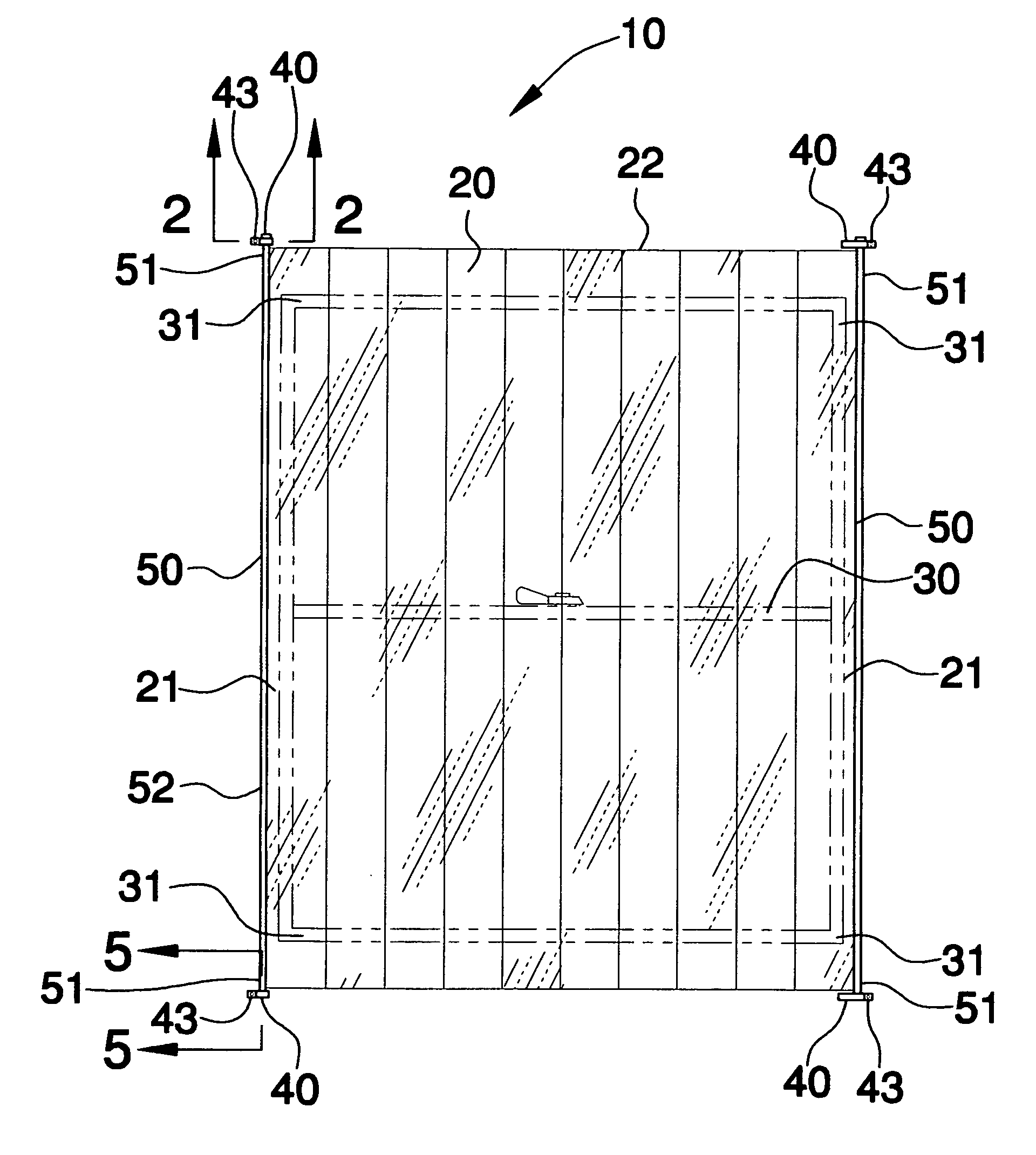
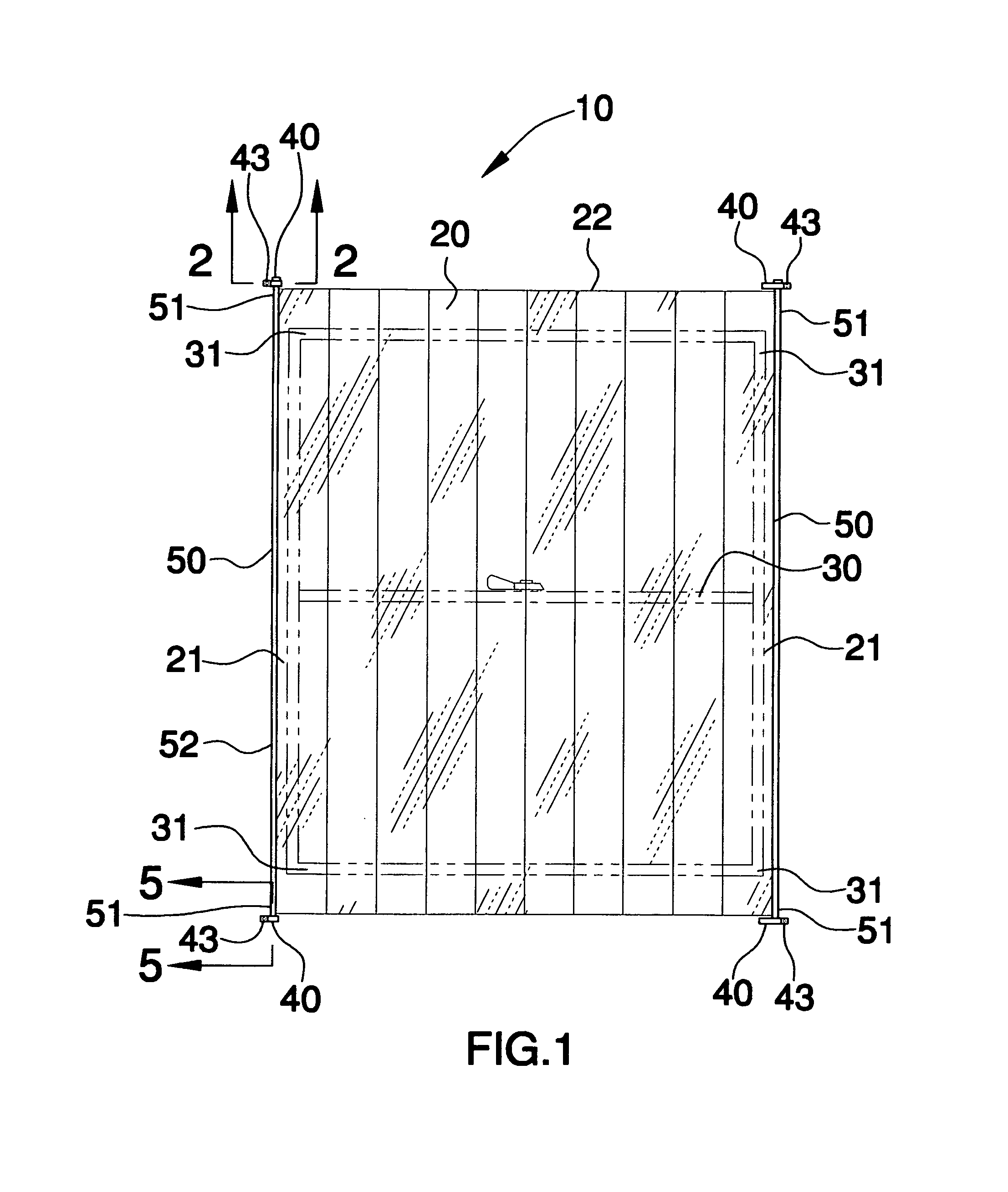
[0013]The apparatus includes a body that has a centrally disposed longitudinal axis and oppositely spaced side portions equally spaced therefrom. The side portion extends substantially parallel to the axis along a length of the body. The body is formed from one-way viewing material for advantageously providing a line of sight extending outwardly through a window but not extending inwardly therethrough. Of course, many conventional one-way viewing materials may be employed by the present invention such as one-way viewing plastics, for example, as well known to a person of ordinary skill in the art. The body is preferably wound about one of the plurality of rods.
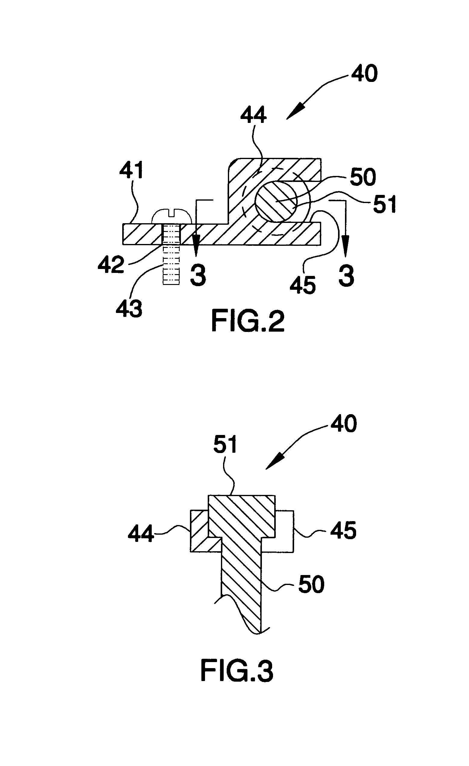
[0014]The apparatus further includes a plurality of brackets secured to a stationary surface adjacent a window and are disposed at opposed corners thereof. The plurality of brackets preferably include a flange portion that has an aperture for receiving a fastening member therethrough r

Problems solved by technology

These blind systems, when shut, impede not only the vision of those from the outside but also the occupants of the residency can not see what is going on outside their own residence.
It is often desirable that they should be able to maintain such surveillance from residencies, but it is usually difficult to do so for any length of time, since persons remaining in a residence with no window covering for extended time periods become highly obvious, and attract both notice and suspicion.
However, while such window coverings of one-way viewing material do permit observations by persons occupying a residence, they do so only imperfectly.

Method used


Image

  • One-way viewing window covering
  • One-way viewing window covering
  • One-way viewing window covering

Examples


Embodiment Construction

[0023]The present invention will now be described more fully hereinafter with reference to the accompanying drawings, in which a preferred embodiment of the invention is shown. This invention may, however, be embodied in many different forms and should not be construed as limited to the embodiment set forth herein. Rather, this embodiment is provided so that this application will be thorough and complete, and will fully convey the true scope of the invention to those skilled in the art. Like numbers refer to like elements throughout the figures.

[0024]The apparatus of this invention is referred to generally in FIGS. 1–6 by the reference numeral 10 and is intended to provide a one-way viewing window covering. It should be understood that the apparatus 10 may be employed in various environments and should not be limited to only residences.

[0025]Referring initially to FIG. 1, the apparatus 10 includes a body 20 that has a centrally disposed longitudinal axis and oppositely spaced side p...


PUM


Abstract

An apparatus positionable across a window includes a body formed from one-way viewing material. The apparatus further includes a plurality of brackets secured to a stationary surface adjacent a window and are disposed at opposed corners thereof. A plurality of elongated rods are attached to opposed side portions of the body. The plurality of rods each has opposed end portions engageable with the plurality of brackets respectively. One of such rods is conveniently movable in a direction substantially transverse to the axis between expanded and retracted positions for advantageously moving the body between stretched and non-stretched positions respectively.

Description

CROSS REFERENCE TO RELATED APPLICATIONS[0001]Not Applicable.STATEMENT REGARDING FEDERALLY SPONSORED RESEARCH OR DEVELOPMENT[0002]Not Applicable.REFERENCE TO A MICROFICHE APPENDIX[0003]Not Applicable.BACKGROUND OF THE INVENTION[0004]1. Technical Field[0005]This invention relates to a window covering and, more particularly, to a one-way viewing window covering for providing increased privacy.[0006]2. Prior Art[0007]Vertical louver type blind systems, similar to Venetian blinds in concept and operation, but formed of a large number of vertically extending elongated blind slats or louvers each pivoted about a vertical center axis for adjustment between open, closed, and desired intermediate positions, and slideable along upper and lower guide tracks have come into wide use as window blind systems, light transmission control or decorative control of transparent partitions or dividers in office space, and similar applications.[0008]More recently, decorative vertical blind systems of simil...

Claims


Application Information

Patent Timeline
IPC IPC(8): A47H23/00
CPCE06B9/24
Inventor HINES, ROBERT
Owner HINES ROBERT
Learn More