Mini fan to be fixed in a recess of a wall

a technology of fan and recess, which is applied in the direction of motors, electrical equipment, electrical apparatus, etc., can solve the problems of more expensive mounting types and other problems

Active Publication Date: 2007-03-06
EBM PAPST ST GEORGEN & -
View PDF7 Cites 31 Cited by
  • Summary
  • Abstract
  • Description
  • Claims
  • Application Information

AI Technical Summary

Benefits of technology

[0010]It is therefore an object of the invention to make available a new mini-fan that can be mounted in simple fashion on a recess of a wall.
[0012]By ingenious “energy management” during the installation operation, the installation of such mini-fans can thus be carried out in very simple and inexpensive fashion, i.e. without tools; an additional advantage achieved is that direct transfer of solid-borne sound from the fan to a surrounding housing is at least greatly reduced. The result is that the fan can be mounted in very simple fashion and with good sealing, the transfer of solid-borne sound from the fan to the adjacent wall occurring only in damped fashion so that the overall noise level is lowered.

Problems solved by technology

This has the disadvantage, however, that solid-borne sound can be transferred by way of this mounting from the fan to a wall, which correspondingly amplifies the noise.
This type of mounting is moreover cost-intensive.

Method used


Image

  • Mini fan to be fixed in a recess of a wall
  • Mini fan to be fixed in a recess of a wall
  • Mini fan to be fixed in a recess of a wall

Examples


first embodiment

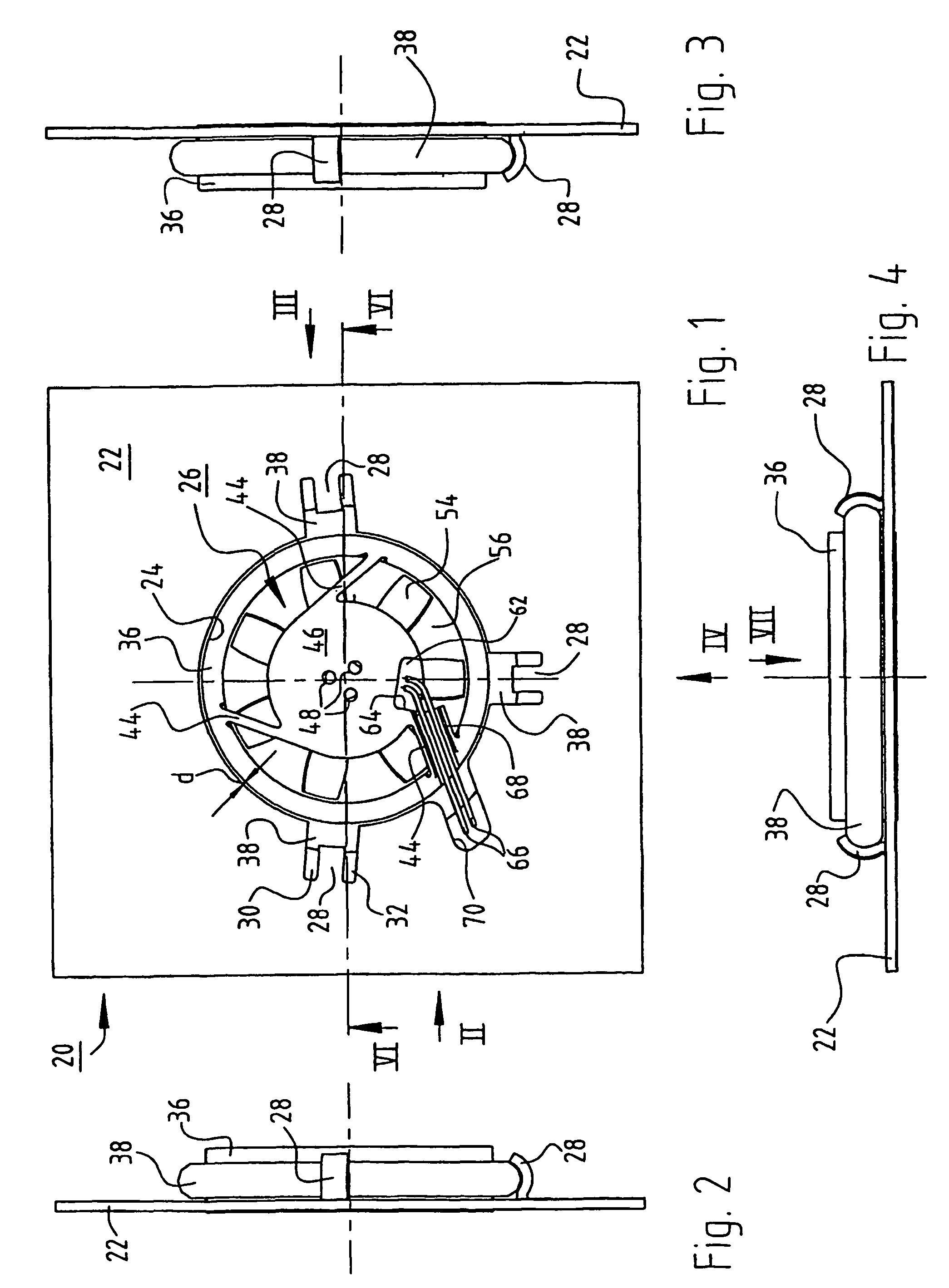
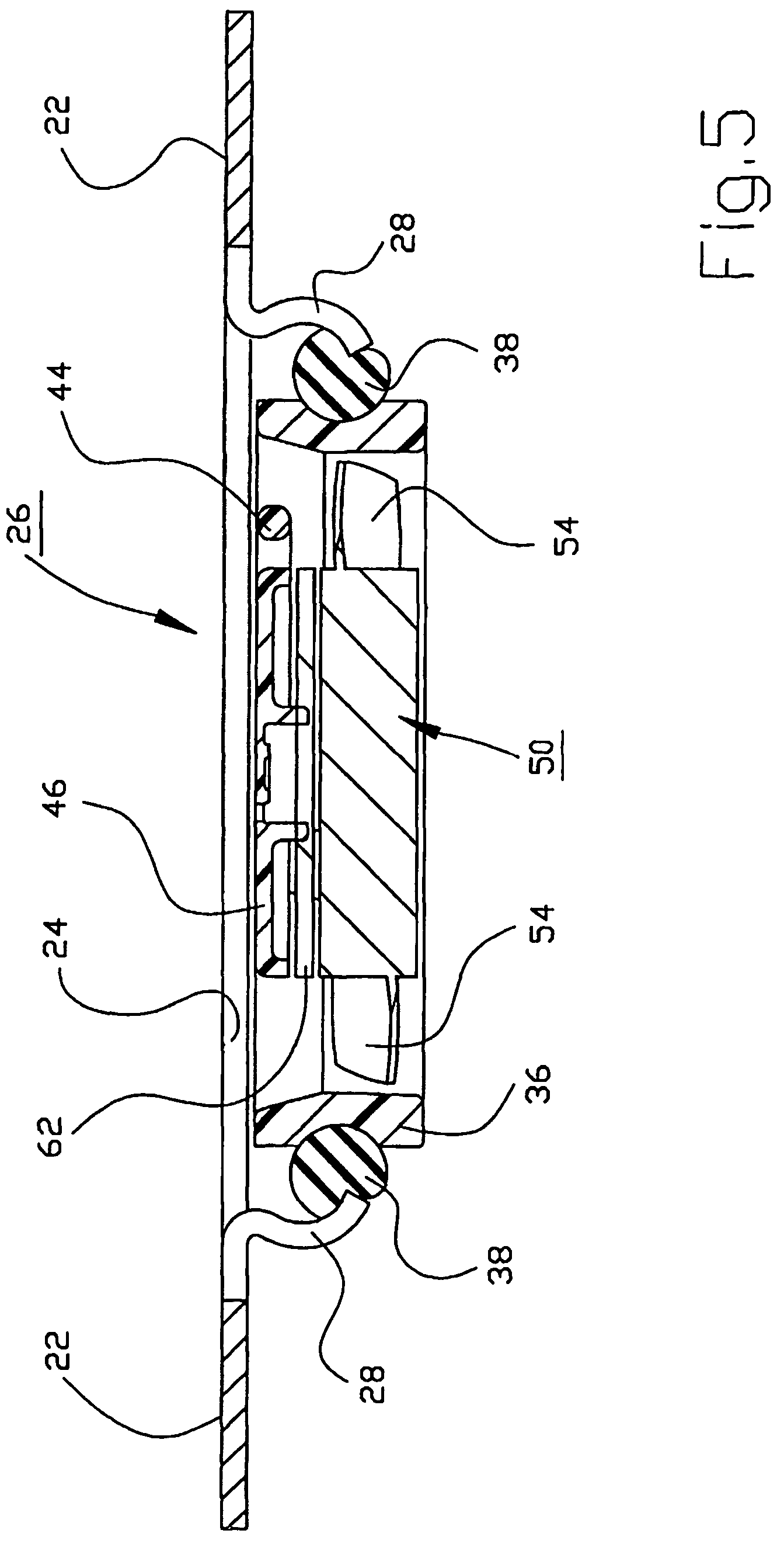
[0030]Implemented at the edge of recess 24 are a plurality of retaining members 28 whose shape is best inferred from FIGS. 1 and 5. In the context of the first embodiment according to FIGS. 1 through 8, retaining members 28 deflect substantially in the radial direction. They are each constituted by two parallel stamped cuts 30, 32 that extend approximately radially outward with respect to recess 24, and they are bent in the manner depicted in FIGS. 5 and 6 to form resilient tabs or retaining prongs that can deflect approximately radially outward upon installation and removal. In the region of their roots, retaining members 28 are preferably provided with a bead 34 for stiffening (see FIG. 7).

[0031]As is apparent in particular from FIG. 6, fan 26 has for air guidance an outer housing part 36 which is substantially round in this embodiment but could also have a different shape, and on which is mounted in suitable fashion an annular elastomeric part, here in the form of an O-ring 38 ma...

second embodiment

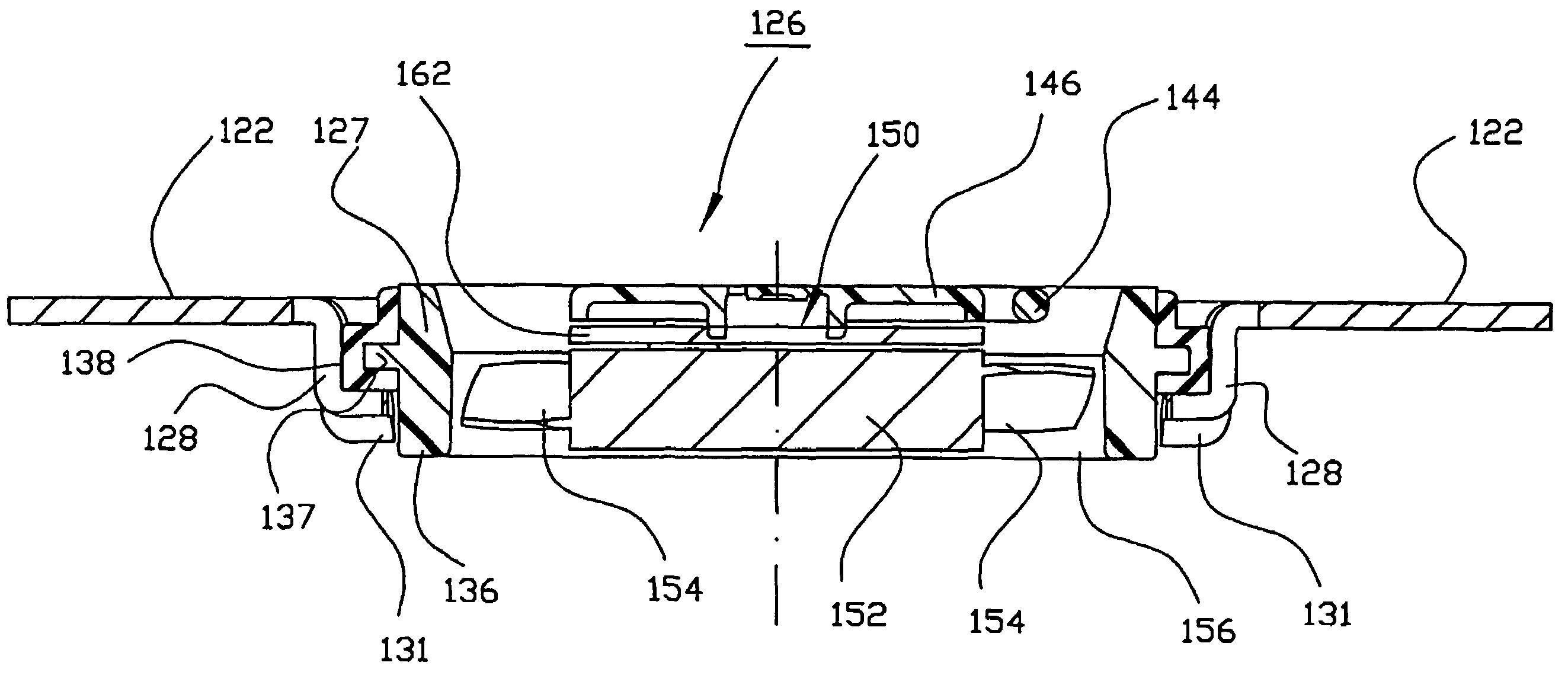
[0038]FIGS. 9 through 15 show a second exemplifying embodiment of the invention. As compared with the embodiment according to FIGS. 1 through 8, the second embodiment is more inexpensive to manufacture, and it makes possible subsequent removal of the fan only with exertion of a great deal of force. In addition, a strain-relief element for the connecting conductors is provided in this variant.

[0039]Commonalities exist between the first and the second embodiment. Identical or identically functioning parts are therefore labeled in FIGS. 9 through 15 with reference characters that are incremented by 100 as compared with FIGS. 1 through 8, e.g. 122 instead of 22. These parts are usually not described again.

[0040]Arrangement 120 has a wall 122 in which is located a recess 124 into which a fan 126 protrudes with a housing portion 127. Recess 124 and housing portion 127 are complementary in shape, e.g. substantially round as depicted.

[0041]A plurality of retaining members or retaining prong...


PUM


Abstract

A mini-fan (126) is implemented for installation in a recess (124) of a wall (122), which wall is equipped on the periphery of the recess (124) with a plurality of retaining members (128, 129). The fan has, for air guidance, a housing (136) that, in its installed position, projects with a housing portion (127) approximately complementary to the recess (124) of the wall (122) into that recess. Arranged on the periphery of that housing portion is at least one part (138) made of an elastomeric material, with which part the fan (126) is introducible, upon its installation with the part (138) made of elastomeric material with displacement along the wall (122), into the retaining members (128, 129), in order to bring that part (138), in the installed position, at least locally into sealing contact against the wall (122).

Description

CROSS-REFERENCE TO RELATED APPLICATIONS[0001]This application is a §371 of PCT / EP2004 / 006102, filed 5 Jun. 2004, which claims priority of DE 203 11 309.8, filed 15 Jul. 2003, which is hereby incorporated by reference.FIELD OF THE INVENTION[0002]The invention concerns a mini-fan for mounting in a recess of a wall.BACKGROUND[0003]Mini-fans, also called miniature or subminiature fans, are used, for example, to cool processors in computers, for equipment cooling in small equipment items, etc., and have very small dimensions.For example:[0004]fans in the ebm-papst 250 series have dimensions of 8×25×25 mm;[0005]those in the ebm-papst 400 F series have dimensions of 10×40×40 mm;[0006]those in the ebm-papst 400 series, 20×40×40 mm; and[0007]fans in the ebm-papst 600 series, 25.4×60×60 mm.[0008]The power consumption of such fans is 0.4–0.6 W for the 250 series, 0.7–0.9 W for the 400 F series, and 0.9–1.6 W for the 400 and 600 series.[0009]With mini-fans, it is usual at present to mount them ...

Claims


Application Information

Patent Timeline
Patent Type & Authority Patents(United States)
IPC IPC(8): F01D25/04F01D25/24F03B1/02F04D25/12F04D29/60F04D29/66H05K7/20
CPCF04D25/12H05K7/20172F04D29/668F04D29/601F04D25/0613
Inventor WINKLER, WOLFGANG ARNORAPP, NILS
Owner EBM PAPST ST GEORGEN & -
Why Eureka
Try Eureka