Matched maneuver detector

a detector and matching technology, applied in the field of automatic target tracking, can solve the problems of affecting the predicted state, affecting the prediction of the future state, and estimating the future state may be in error

Active Publication Date: 2007-03-06
LOCKHEED MARTIN CORP
View PDF39 Cites 15 Cited by
  • Summary
  • Abstract
  • Description
  • Claims
  • Application Information

AI Technical Summary

Benefits of technology

[0009]A method for maneuver detection in a target tracking context includes the steps of generating data relating to the state of a target. This data may include position and velocity, velocity and acceleration, or other derivatives or integrals of position and rate of change of position. The method also includes the step of predicting the state of the target at a selected time by use of a predictor having a known response to an instantaneous change in velocity...

Problems solved by technology

If such a predictor is used in a situation in which the target accelerates, the prediction of the future state may be in error.
Put a...

Method used


Image

  • Matched maneuver detector
  • Matched maneuver detector
  • Matched maneuver detector

Examples


Embodiment Construction

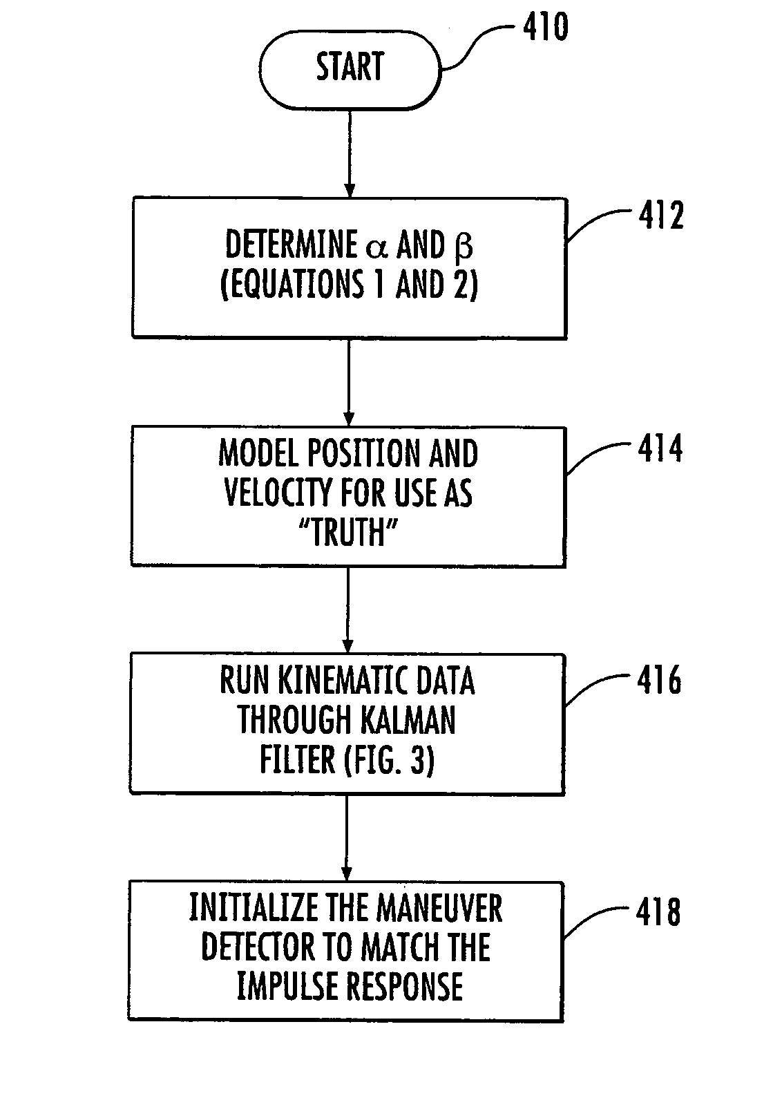
[0015]The invention is based upon the understanding that the frequency characteristics of the maneuver detector should match the impulse response of the predictor of the Kalman filter tracking system. A maneuver is declared when the value of the output of the matched-filter maneuver detector exceeds a given value or threshold.

[0016]In general, the assumption is made for purposes of determining the response of the Kalman filter that the target has been flying with a fixed velocity, and at some moment in time undergoes impulse acceleration. Thus, the target is assumed to change velocity instantaneously from the original fixed velocity to a new velocity. This corresponds to an infinite velocity slope, corresponding to an acceleration impulse. This is a convenient mathematical fiction which allows testing or modeling of the residual response of the Kalman filter. The modeling of the residual response characterizes the frequency response of the residual. The maneuver detector in the prio...


PUM


Abstract

A target tracking arrangement predicts the state of a target. The predictor may be a Kalman filter. In the presence of a target which is maneuvering, the prediction may be in error. A maneuver detector is coupled to receive residuals representing the difference between the predictions and the target state. The maneuver detector is matched to the predictor or Kalman filter to thereby tend to reduce the undesirable effects of system noise. The matching may be of the frequency response.

Description

FIELD OF THE INVENTION[0001]This invention relates to automatic target tracking, and more particularly to target maneuver detection in automatic tracking systems.BACKGROUND OF THE INVENTION[0002]Automatic tracking systems are widely used for various military and nonmilitary purposes. Among the military purposes are the determination of the locations of airborne, undersea, and seaborne vehicles in a region to be controlled, and the automatic control of weapons directed toward such targets. Air traffic and harbor traffic control are among the civilian or peacetime uses of automatic tracking systems.[0003]FIG. 1 is a simplified block diagram of a prior-art target tracking system 10. In FIG. 1, a sensor or sensor array designated 12 observes a region 14 in which one or more targets T are maneuvering. An arrow 16 illustrates the instantaneous velocity of target T. Sensor 12 may be a radar, sonar, or lidar system, a staring optical array, an acoustic system, or any sensor which is capable...

Claims


Application Information

Patent Timeline
IPC IPC(8): G01S13/66G01S13/06G01S15/06G01S15/66G01S17/06G01S17/66G01S13/00G01S15/00G01S17/00
CPCG01S13/723G01S17/66G01S15/66
Inventor YANG, ROBERT E.
Owner LOCKHEED MARTIN CORP
Why Eureka
Try Eureka