
Antenna structure for devices with conductive chassis

a technology of conductive chassis and antenna structure, which is applied in the direction of resonant antenna, antenna earthing, collapsable antenna means, etc., can solve the problems of affecting the styling and distinctiveness of the product, and the performance of the clam shell cellular phone antenna when mounted on the metal chassis

Active Publication Date: 2007-03-06
GOOGLE TECHNOLOGY HOLDINGS LLC
View PDF6 Cites 23 Cited by
  • Summary
  • Abstract
  • Description
  • Claims
  • Application Information

AI Technical Summary

Benefits of technology

The present invention relates to wireless communication devices. The invention provides a wireless communication device with an antenna that can be extended and retracted. The device has a conductive portion on the flip cover that is connected to ground within the device. The invention also includes a dielectric substrate that maintains the resonant frequency of the antenna when the antenna is extended or retracted. The technical effects of the invention include improved wireless communication and flexibility in antenna usage.

Problems solved by technology

A recognized problem with using a flip phone design is that the performance of a clam shell cellular phone antenna is degraded when mounted on a metal chassis phone.
Increasing the antenna dimensions, however, negatively impacts the styling and distinctiveness of the product.

Method used


Image

  • Antenna structure for devices with conductive chassis
  • Antenna structure for devices with conductive chassis
  • Antenna structure for devices with conductive chassis

Examples


Embodiment Construction

[0013]As required, detailed embodiments of the present invention are disclosed herein; however, it is to be understood that the disclosed embodiments are merely exemplary of the invention, which can be embodied in various forms. Therefore, specific structural and functional details disclosed herein are not to be interpreted as limiting, but merely as a basis for the claims and as a representative basis for teaching one skilled in the art to variously employ the present invention in virtually any appropriately detailed structure. Further, the terms and phrases used herein are not intended to be limiting; but rather, to provide an understandable description of the invention.

[0014]The terms “a” or “an”, as used herein, are defined as one or more than one. The term plurality, as used herein, is defined as two or more than two. The term another, as used herein, is defined as at least a second or more. The terms including and / or having, as used herein, are defined as comprising (i.e., ope...


PUM


Abstract

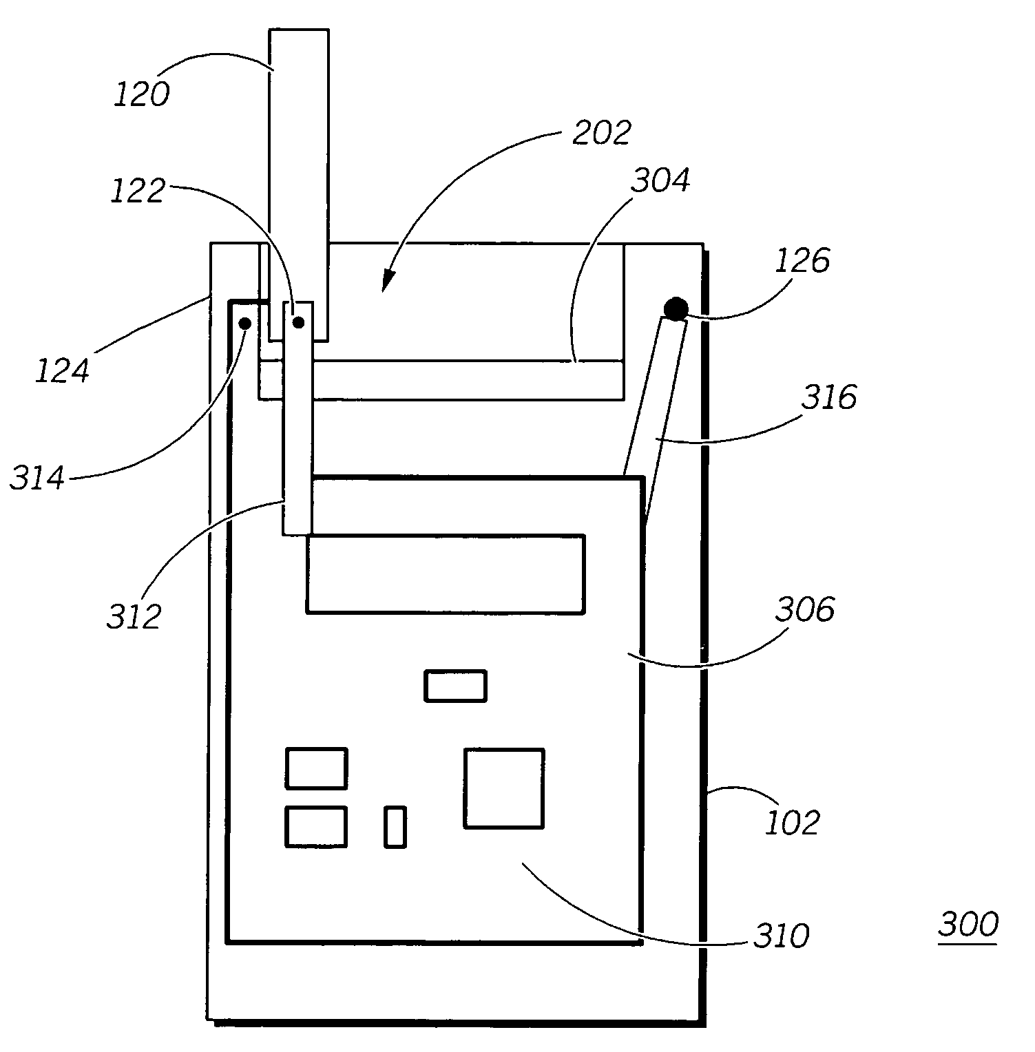
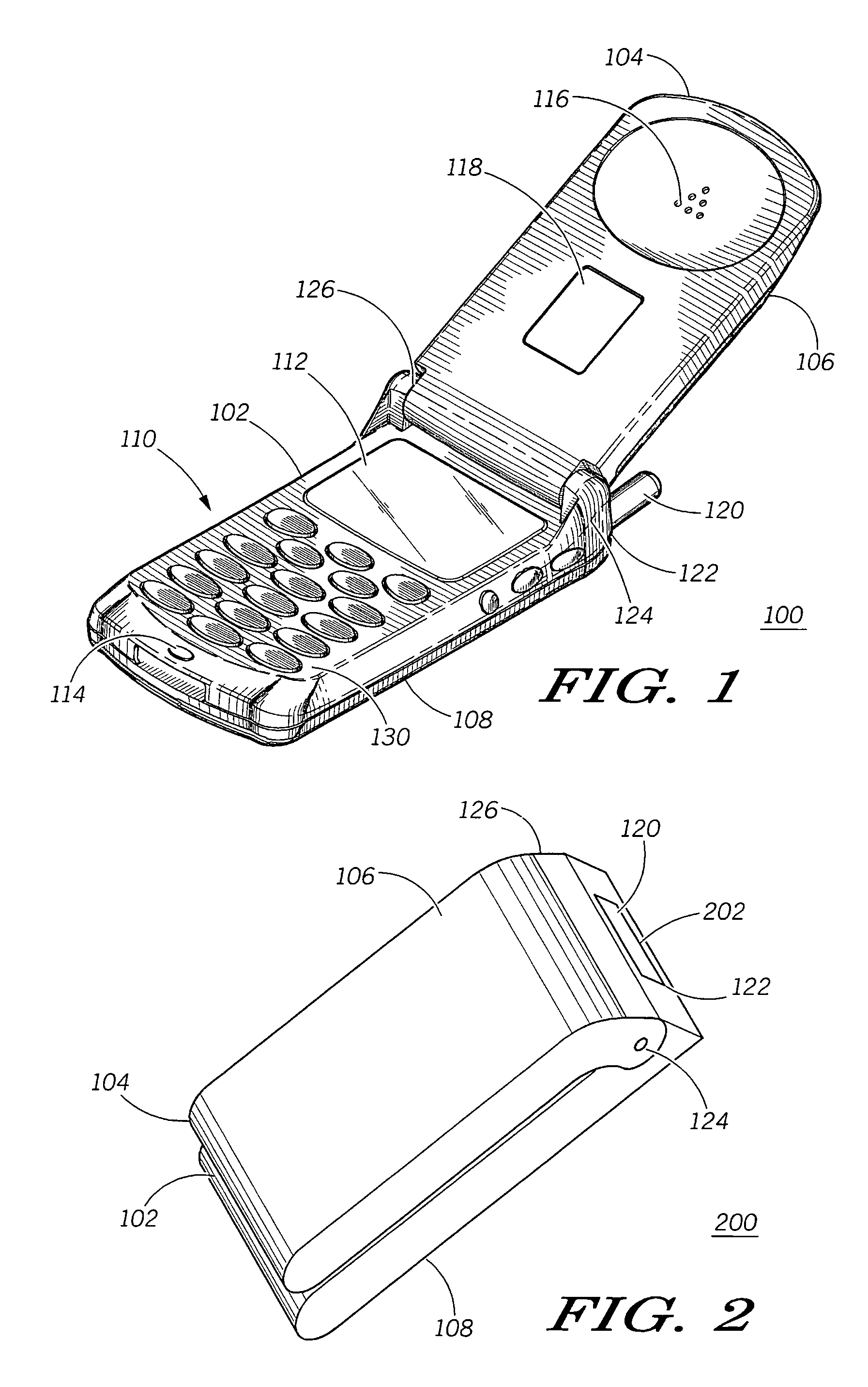
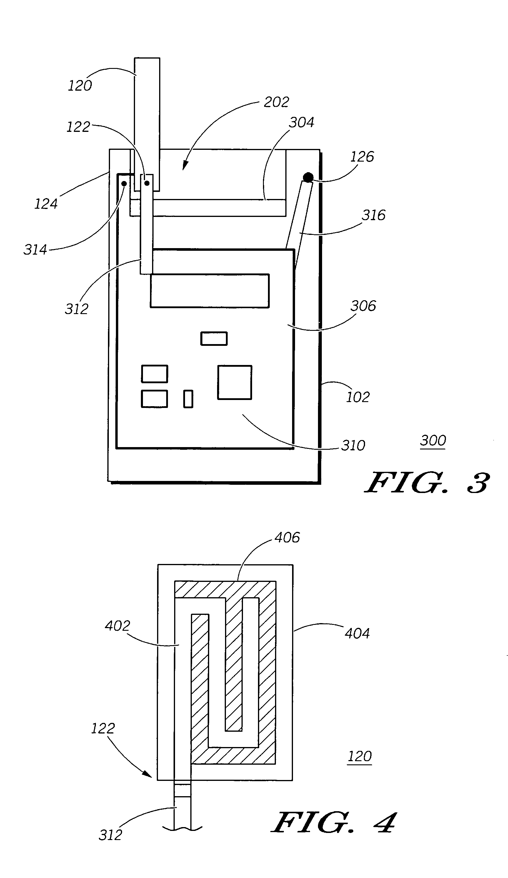
A multiband element antenna (120) used in combination with a unique metal chassis design that enhances antenna performance and that enables the design of a compact and efficient antenna system. A cellular flip phone (100) that has a conductive chassis includes a flip up antenna (120) that pivots between an extended and a retracted position. The antenna (120) pivots at a point that is located on one edge of the top of the cell phone body (102). The conductive chassis of the flip cover (104) is grounded to the flip phone body (102) at a single point or single surface that is substantially opposite the antenna RF feed (122). Conductive surfaces of the cellular flip phone body (102) are grounded at a single point that is near the antenna RF feed point (122). This grounding arrangement has been found to control the flow of induced currents on the conductive portions of the flip cover (104) and body (102), thereby improving the performance of the device's antenna (120).

Description

FIELD OF THE INVENTION[0001]The present invention generally relates to the field of wireless communications devices and more particularly to radio antenna designs for incorporation into wireless communications devices.BACKGROUND OF THE INVENTION[0002]Portable communications devices, such cellular telephones, are becoming more compact and adapting distinct design features. One design that provides both functional and aesthetical benefits is the flip-phone design. The flip phone design has a cover that flips from a closed or folded position to an open or extended position. The cover may contain a speaker or microphone so that when the cover is placed into its extended position, the cover is able to act as part of the phone structure and extend the earpiece or microphone away from the body of the phone. This allows the body of the phone to be correspondingly smaller.[0003]A recognized problem with using a flip phone design is that the performance of a clam shell cellular phone antenna ...

Claims


Application Information

Patent Timeline
Patent Type & Authority Patents(United States)
IPC IPC(8): H04M1/00H01Q1/24H04MH04Q7/20
CPCH01Q1/243H01Q1/38H01Q1/48H04B1/3833H04M1/0214
Inventor PONCE DE LEON, LORENZO A.CANDAL, ALEJANDROCHENOWETH, JOHN P.MINASI, DAVID HARTLEY
Owner GOOGLE TECHNOLOGY HOLDINGS LLC
Learn More