Method for improving the magnitude of compressive stress developed in the surface of a part

a compressive stress and magnitude technology, applied in the field of improving the magnitude of compressive stress developed in the surface of a part, can solve the problems of reducing both fatigue life and increasing corrosion sensitivity, and surface residual stress being known to have a major influence on the fatigue and stress corrosion performance of components or parts in servi

Active Publication Date: 2007-03-13
SURFACE TECH HLDG
View PDF3 Cites 24 Cited by
  • Summary
  • Abstract
  • Description
  • Claims
  • Application Information

AI Technical Summary

Problems solved by technology

Surface residual stresses are known to have a major affect upon the fatigue and stress corrosion performance of components or parts in service.
Tensile residual stresses that can be developed during manufacturing processes, such as grinding, turning, or welding are well known to reduce both fatigue life and increase sensitivity to corrosion-fatigue and stress corrosion cracking in a wide variety of materials.
However, the benefit of inducing a layer of surface compression in reducing susceptibility to stress corrosion, cracking, fatigue, and corrosion-fatigue is lost if the layer of compression relaxes with time in service.
Many components and parts of practical interest are subject to high tensile cyclic loads or high mean loads that often lead to fatigue, corrosion fatigue, stress corrosion, or a combination of such failure modes.
Unfortunately, both approaches require a secondary surface treatment unrelated to the original burnishing process thereby adding time, cost, and the potential for damage and the loss of the part during manufacture.
Shot peening while being relatively inexpensive and preferred for many applications, is often unable to obtain the necessary coverage of the part without overlaping areas of impingement.
Such overlapping often results in relatively large amount of cold working which may leave the surface compressive layer susceptible to stress relaxation.
Further, shot peening is often unacceptable for use in manufacturing parts requiring a superior finish, localized or relatively complex compressive stress zones or patterns, or requiring a greater depth of compressive stress penetration.

Method used


Image

  • Method for improving the magnitude of compressive stress developed in the surface of a part
  • Method for improving the magnitude of compressive stress developed in the surface of a part
  • Method for improving the magnitude of compressive stress developed in the surface of a part

Examples


Embodiment Construction

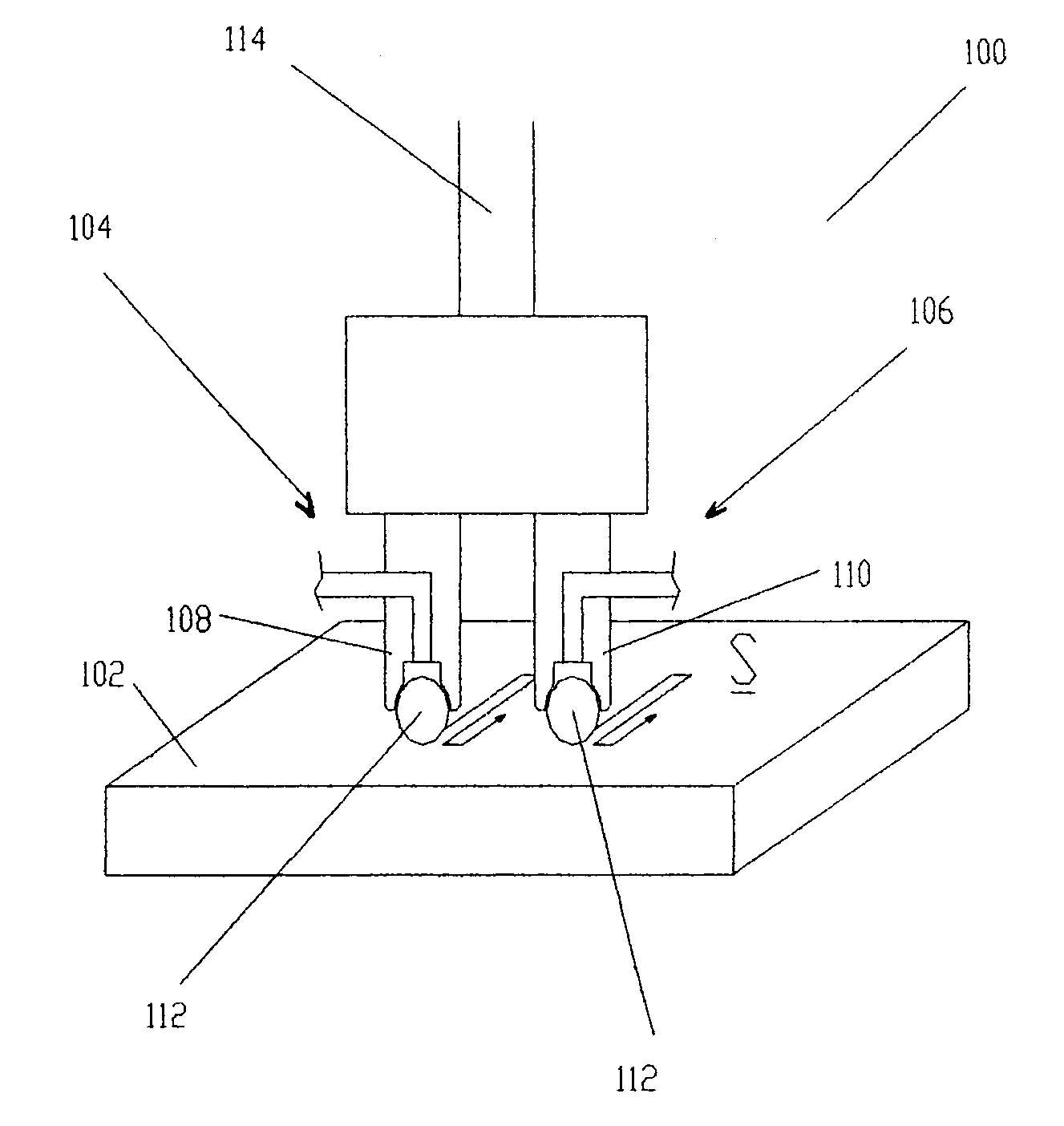
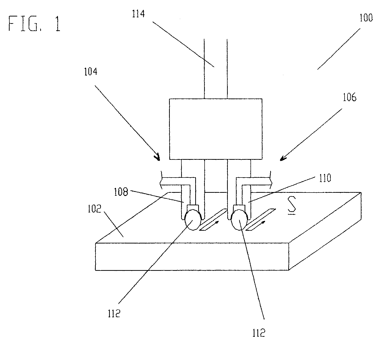
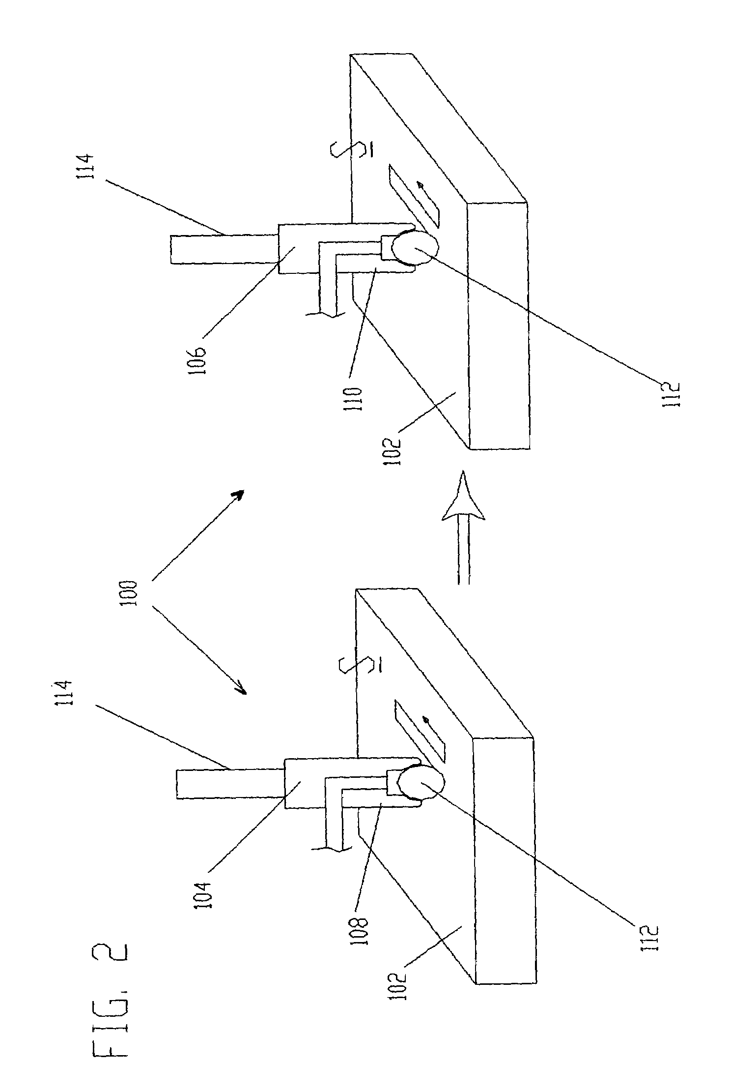
[0035]The present invention relates to a method and apparatus for performing the method of inducing compressive residual stress along a selected region of a part. In describing the preferred embodiments of the invention illustrated in the drawings, specific terminology will be resorted to for the sake of clarity. However, the invention is not intended to be limited to the specific terms so selected, and it is to be understood that each specific term includes all technical equivalents that operate in a similar manner to accomplish a similar purpose.

[0036]It has been found that the effect of secondary burnishing or deep rolling either parallel or perpendicular to the original path of the burnishing apparatus using the same burnishing member diameter and compressive loads have shown to have no significant effect on the residual stress developed. In order to facilitate the introduction of greater compressive residual stresses in a part, deep rolling and other conventional burnishing tec...


PUM

PropertyMeasurementUnit
temperatureaaaaaaaaaa
residual compressive stressesaaaaaaaaaa
compressive stressesaaaaaaaaaa

Abstract

This invention relates to a method and an apparatus for performing the method of inducing compressive residual stress along the surface of a part. In the preferred embodiment of the invention, the method includes burnishing or deep rolling a surface using a first and a second roller or ball burnishing members, whereby the first and second burnishing members may have a different diameter and / or modulus of elasticity. In another preferred embodiment of the invention, the burnishing operations may be performed while the surface of the part is at different temperatures.

Description

BACKGROUND OF THE INVENTION[0001]This invention relates to a method and an apparatus for performing the method of inducing compressive residual stress along the surface of a part and, more particularly, to a method and an apparatus for performing the method of burnishing or deep rolling a surface of a part whereby the magnitude and penetration of compressive residual stress achieved is greater than that achieved by conventional burnishing.[0002]Surface residual stresses are known to have a major affect upon the fatigue and stress corrosion performance of components or parts in service. Tensile residual stresses that can be developed during manufacturing processes, such as grinding, turning, or welding are well known to reduce both fatigue life and increase sensitivity to corrosion-fatigue and stress corrosion cracking in a wide variety of materials. It is also known that compressive residual stresses induced in the surface of a part can increase its fatigue life and reduce its susce...

Claims


Application Information

Patent Timeline
Patent Type & Authority Patents(United States)
IPC IPC(8): B24B39/00B23P9/02C21D7/08
CPCB23P9/02B24B39/00C21D7/08Y10T29/47Y10T29/476
Inventor PREVEY, PAUL S.
Owner SURFACE TECH HLDG
Why Eureka
Try Eureka