
Front derailleur for a bicycle

a technology for derailleurs and bicycles, applied in mechanical devices, gearing, transportation and packaging, etc., to achieve the effect of minimizing the operation force required and reliably affecting the operation of the change speed

Inactive Publication Date: 2007-03-13
SUN ACE STURMEY ARCHER
View PDF5 Cites 16 Cited by
  • Summary
  • Abstract
  • Description
  • Claims
  • Application Information

AI Technical Summary

Benefits of technology

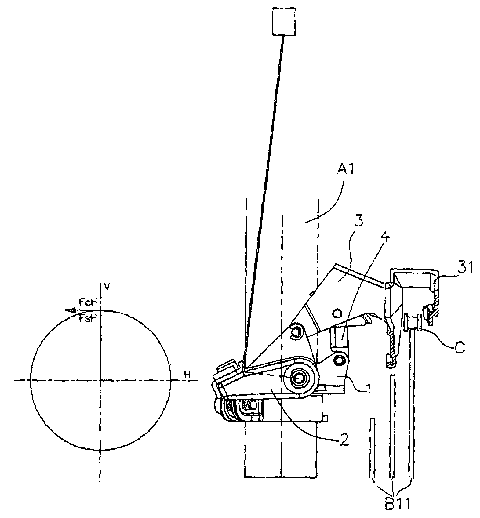
"The present invention provides an improved bicycle front derailleur that can reliably effect a change speed operation with the aid of a sufficient restoring force of a return spring and achieve minimized in operation forces required for various change speeds. The linkage mechanism of the front derailleur is designed in a way that the restoring force provided by the return spring is equal to an active component force for actually shifting the chain, which means that the restoring force can be utilized fully for down-shifting. This results in a more efficient and effective shifting performance of the bicycle."

Problems solved by technology

However, because the control cable could only transmit tension, the front derailleur must implant a return spring to provide a return force for pulling the chain guide inwardly, while the tension released.

Method used


Image

  • Front derailleur for a bicycle
  • Front derailleur for a bicycle
  • Front derailleur for a bicycle

Examples


Embodiment Construction

[0031]The following embodiments will illustrate the front derailleur for a bicycle of the present invention in detail.

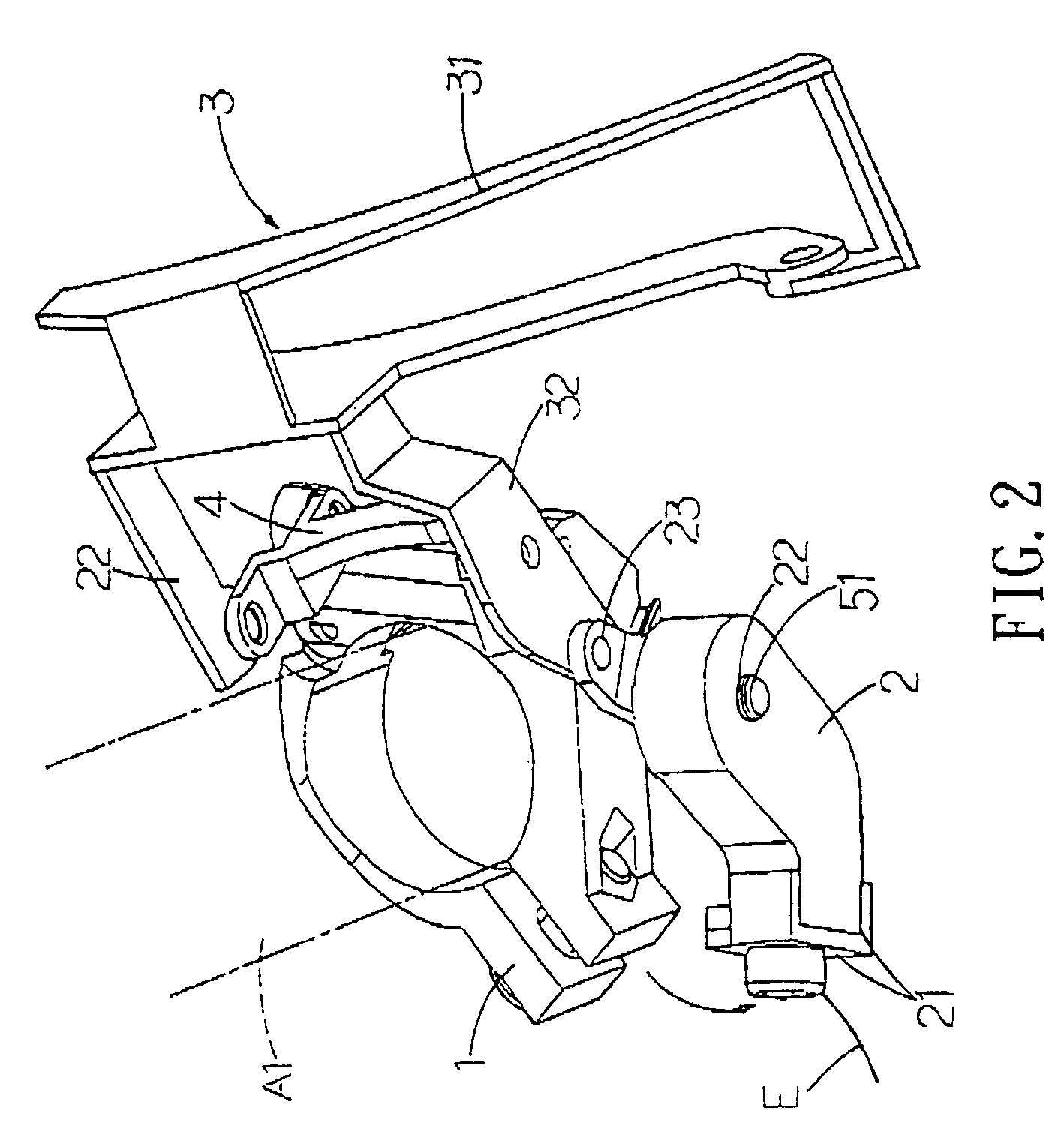
[0032]With reference to FIG. 6 and FIG. 7, a preferred embodiment of the present invention is presented illustrating a bicycle front derailleur comprises: a frame bracket 1 having a pair of lugs 11 disposed at the side thereof close to the chainwheel B1 for connecting with the seat tube A1; a chain guide 3 comprising a guide plate 31 overstriding the chain C and a pivot joint 32 formed at the opposite side of the guide plate 31; a linkage rod 4 having one of its end pivotally connected to the lug 11, and the other end pivotally connected to the pivot joint 32; an actuating arm 2 is pivotally connected to the frame bracket 1 through two shaft hole 12, 22, which are located respectively at one side of the lug 11 of the frame bracket 1 and at middle section of the actuating arm 2, using a shaft 51 installed with a return spring 52, furthermore, the actuating arm 2 compr...


PUM


Abstract

The present invention provides a bicycle front derailleur mountable to a seat tube of a bicycle frame for fitting a chain around a selected sprocket of a multiple chainwheel by pushing the chain laterally at a portion thereof advancing into engagement with the chainwheel, the front derailleur comprising: a fixed section fixed to a bicycle frame, a chain guide for contacting a chain to shift the chain, and an actuating arm and a linkage rod disposed between and pivotally connected to the fixed section and the chain guide. In the above construction, the present invention has achieved the intended object of providing an improved bicycle front derailleur capable of reliably effecting a change speed operation with the aid of a sufficient restoring force of the return spring and achieving minimized in operation forces required for various change speeds.

Description

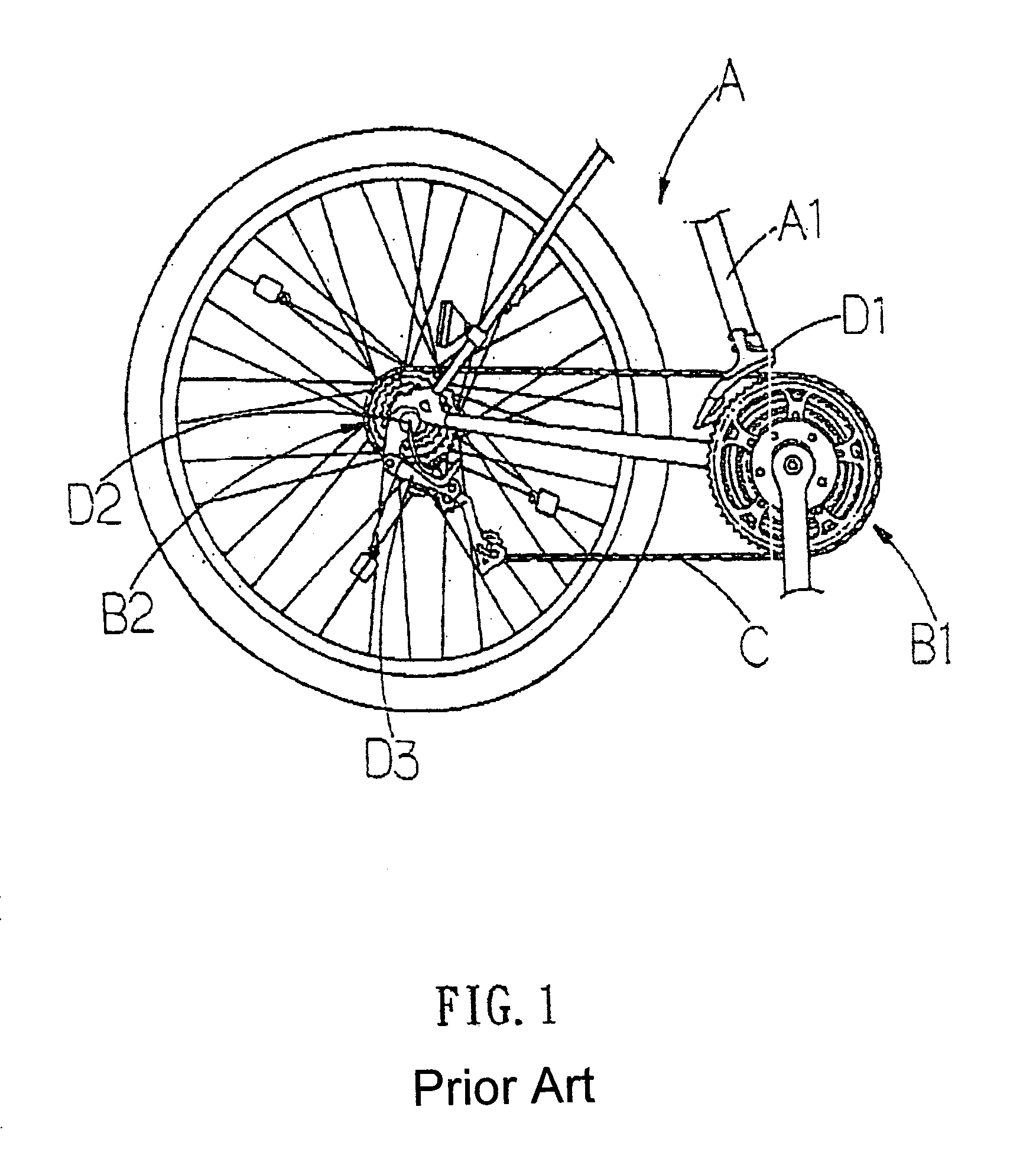
BACKGROUND OF THE INVENTION[0001](a). Field of the Invention[0002]The present invention relates to a front derailleur for a bicycle, and more specifically to a front derailleur for a bicycle that can achieve efficiency and stability during a shifting operation.[0003](b). Description of the Prior Arts[0004]A bicycle is commonly used as a transportation vehicle; and widely employed as a sport machine. Basically, the bicycle includes several parts, such as transmission system, brake system, frame, and so on, although these parts vary from different types of bicycles. The frame constructs the main body of a bicycle. The transmission system which is a mechanism in combination of chain, chainwheel, freewheel, pedal, and soon, plays a role to transmit a force generated from cyclist to drive the bicycle. In the derailleur system for a bicycle A, as shown in FIG. 1, which includes a seat tube A1, a chainwheel B1, a freewheel B2, a chain C, a front derailleur D1, a rear derailleur D2, a rocki...

Claims


Application Information

Patent Timeline
Patent Type & Authority Patents(United States)
IPC IPC(8): F16H9/00B62M9/1342B62M9/1348B62M9/135B62M9/136B62M9/137
CPCB62M9/1342B62M9/136B62M9/1348
Inventor TSAI, MING-CHIHSHENG, YAN-LONG
Owner SUN ACE STURMEY ARCHER
Learn More