Self-reset valve

a self-reset and valve technology, applied in the direction of valve details, valve arrangement, thin material handling, etc., can solve the problems of inconvenient user operation and inability to guarantee the reliability of the switch

Active Publication Date: 2014-06-03
XIAMEN SOLEX HIGH TECH IND CO LTD
View PDF20 Cites 4 Cited by
  • Summary
  • Abstract
  • Description
  • Claims
  • Application Information

AI Technical Summary

Benefits of technology

[0024]1. With the stop mechanism, the clutch and the reset elastic body, the drive shaft rotates forward and drives the clutch rotate forward by the clutch, making sure that the water diversion body stays still when the drive shaft rotates backward and resets. So it can be self-reset and the drive shaft is positioned in the same position despite the state of the shower. it's convenient for the user's operation. The rotary angle is determinate by the ratch, making the switch accurately.
[0025]2. The clutch includes inner ratch, assembly groove, elastic body and play block, the play block works on the inner ratch by the withstanding of the elastic body, the switch is energy saving with minimized operation force.
[0028]5. The water diversion body includes a plate and a perispore, the inner revolution surface of the perispore is disposed with inner ratch, the outer revolution surface of the plate is disposed with outer ratch, it can be easily machined to couple to the clutch and stop mechanism.

Problems solved by technology

The existing rotary valve has disadvantages as below: firstly, as the drive shaft and the rocker can not self-reset, they are positioned in different place in different status, which is not convenient for the user's operation; secondly, as the water diversion body, the drive shaft and the rocker are fixed together, whether the rotary of the water diversion body is positioned accurately is controlled by the rocker, it may be over rotated or not rotated enough.
It's unable guarantee the reliability of switch.

Method used


Image

  • Self-reset valve
  • Self-reset valve
  • Self-reset valve

Examples


Embodiment Construction

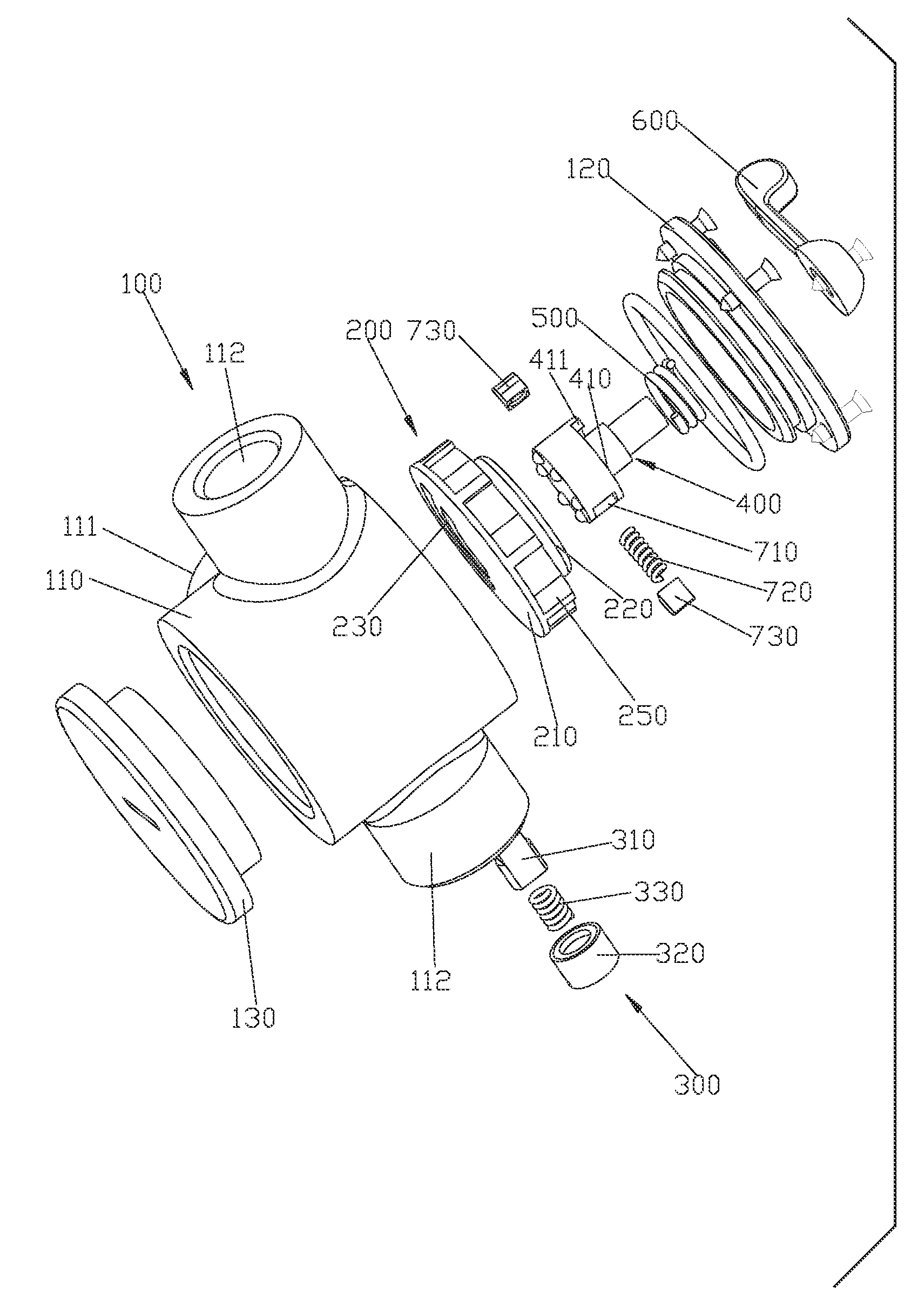
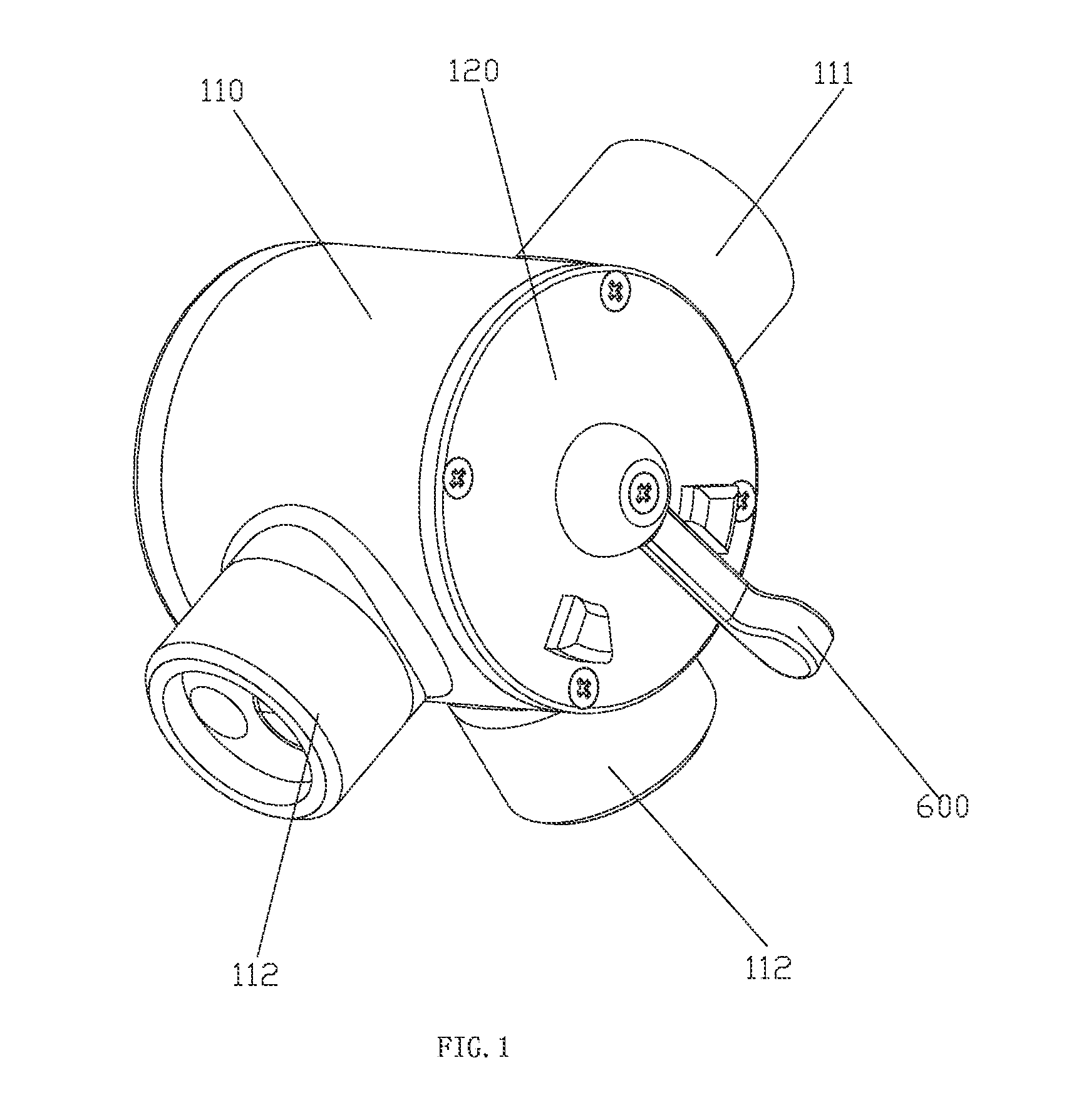
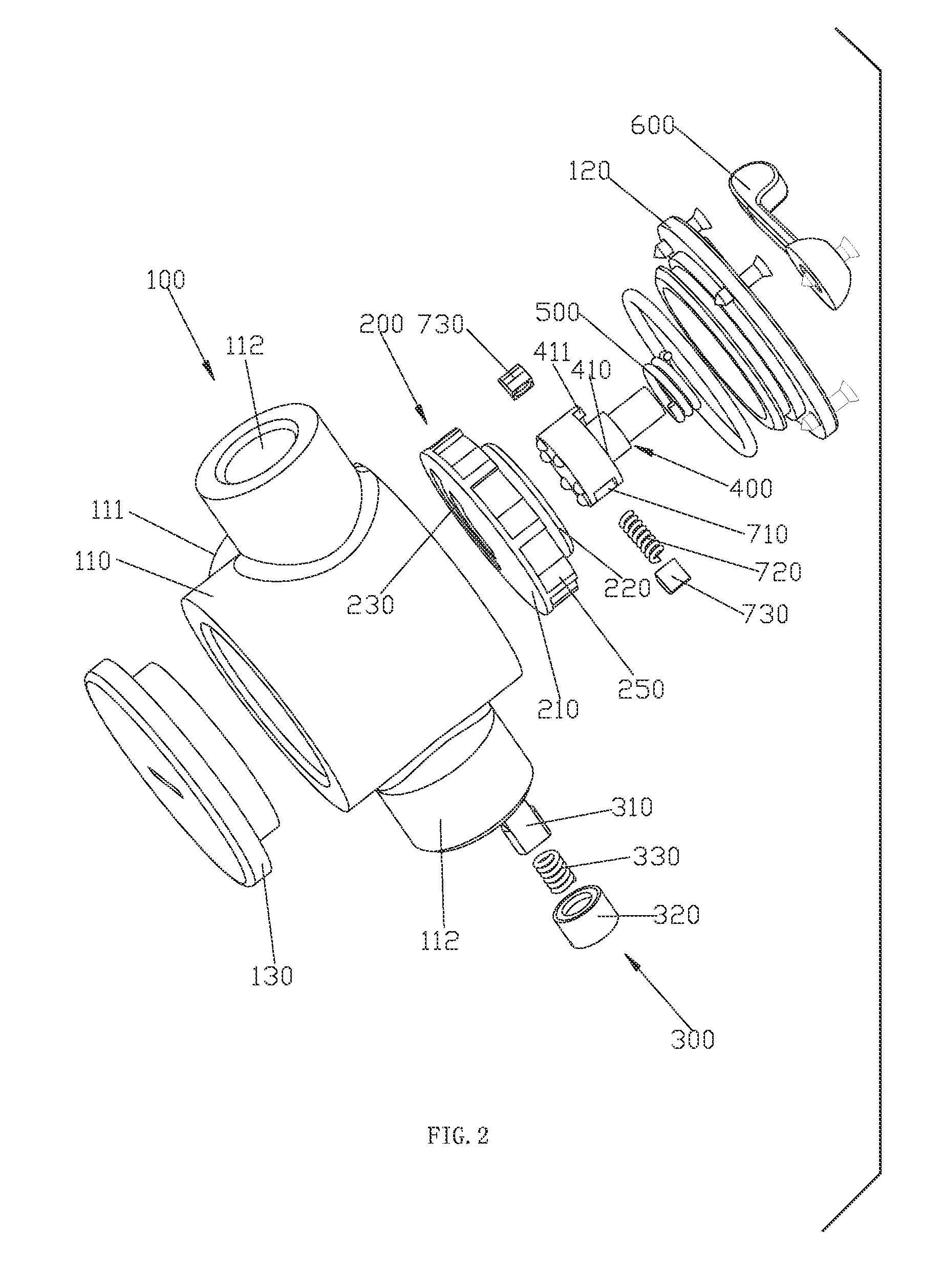
[0043]Please refer to the FIG. 1 to the FIG. 12; a self-reset valve includes a fixed unit 100, a water diversion body 200, a stop mechanism 300, a drive shaft 400, a clutch, a reset elastic body 500 and a rocker 600.

[0044]Please refer to the FIG. 1 to FIG. 2, especially the FIG. 2, FIG. 3 and FIG. 7. The fixed unit 100 includes a main body 110, an upper cover 120 and a lower cover 130.

[0045]The main body 110 is tubular shaped and disposed with an inlet hole 111 and two outlet holes 112. The inlet 110 is connected to the water source, while the two outlet holes 112 are separately connected to two outlet functions; the main body 110 has an inner hole, which is disposed with a division board 113. The division board 113 is disposed with water diversion holes 114 of same set number with the outlet holes 112. the water diversion holes 114 are separately connected to the outlet holes one to one correspondence. In this embodiment, each set of water diversion holes 114 includes two water div...


PUM


Abstract

A self-reset valve has a fixed unit, a water diversion body, a stop mechanism, a drive shaft and a clutch. The fixed unit is disposed with an inlet waterway and at least two waterways. The water diversion body is rotatably connected to the fixed unit inside. The water diversion body is disposed with an outer revolution surface having an outer ratch and an inner revolution surface. The stop mechanism is connected to the fixed unit and acted on the outer ratch. The drive shaft is rotatably connected to the fixed unit. The drive shaft is disposed with a control end and a drive end. The clutch is connected between the drive end of the drive shaft and the inner revolution surface of the water diversion body. The reset elastic body is connected between the drive shaft and the fixed unit.

Description

FIELD OF THE INVENTION[0001]The present invention relates to a self-reset valve.BACKGROUND OF THE INVENTION[0002]The existing rotary valve includes a fixed unit, a water diversion body, a drive shaft and a rocker. The fixed unit has an inlet waterway and at least tow outlet waterways. The water diversion body is rotatably connected to the fixed unit inside, and the switch of the outlet waterways to connect to the inlet waterway is realized by the relative rotary of the water diversion body and the fixed unit. The drive shaft is disposed with a fixed end and a control end, the fixed end is fixed to the water diversion body, while the control end is extended out of the fixed unit to be fixed to the rocker. The existing rotary valve has disadvantages as below: firstly, as the drive shaft and the rocker can not self-reset, they are positioned in different place in different status, which is not convenient for the user's operation; secondly, as the water diversion body, the drive shaft a...

Claims


Application Information

Patent Timeline
Patent Type & Authority Patents(United States)
IPC IPC(8): F16K11/074
CPCF16K31/44F16K11/0743F16K31/047Y10T137/86871Y10T137/7723Y10T137/86501
Inventor ZHOU, HUASONGZHONG, YANHUIPENG, HAISONGLI, QINGSHUANG
Owner XIAMEN SOLEX HIGH TECH IND CO LTD
Why Eureka
Try Eureka