Tubular case

a tube and case technology, applied in the field of tube cases, can solve the problems of affecting the operation of detachment of the cap, and achieve the effects of reducing the operating force, easy mounting, and large rotation angl

Active Publication Date: 2010-09-21
KOKUYO CO LTD
View PDF13 Cites 3 Cited by
  • Summary
  • Abstract
  • Description
  • Claims
  • Application Information

AI Technical Summary

Benefits of technology

[0022]According to the present invention, the peripheral member has a shape that substantially encloses the periphery of the case and the force apply points are located at the symmetrical points distanced away from the rotation center. Accordingly, a force for imparting an operating force to the operating member to release the engagement of the cap can be reduced, and a force for moving the cap in a direction of release from the engagement can be evenly dispersed. When the peripheral member constituting the operating member has a closed loop shape, the force apply points can be located as far as possible away from the rotation center to minimize the operating force. Moreover, the operating force imparting portion is not required to be protruded largely from the peripheral member. Accordingly, the operating member can be designed integrally with the tubular case in appearance thereby decreasing such a case that the unexpected operating force is applied thereon.
[0023]Also, such an arrangement is adopted that, when the peripheral member is rotated and displaced, the force apply points only come into contact with the end portions at the open side of the cap peripheral wall. That is, since the portion between the force apply points is kept in a non-contact state, a large rotation angle can be ensured for the operating member, and thus the cap can be detached from the case with a force small enough to pick up the same.
[0024]In an arrangement that the peripheral member is formed in a substantially C-like shape in plane view and the force apply points are formed at the open side of the C-like shape, the operating member can be easily mounted onto the case. Compared to the case of U-like shape in plane view, the force apply points can be located relatively far away from the rotation center, thus such a disadvantage is not brought about that large operating force is required.
[0025]Further, in an arrangement that a rotation center forming portions for forming the rotation center of the cap is arranged in the case, the cap can be released from the engagement with a stable rotation of the cap.
[0026]Furthermore, in an arrangement that a stopper mechanism is provided between the case and the peripheral member, the operating member is prevented from being accidentally rotated, thereby ensuring the cap being reliably attached on the case.

Problems solved by technology

However, since the cap has a relatively short cylindrical shape with respect to the length of the entire tubular case, the cap has a disadvantage such that fingers are slippery while releasing the cap from the engagement which causes a burdensome operation to detach the cap.

Method used


Image

  • Tubular case
  • Tubular case
  • Tubular case

Examples


Embodiment Construction

[0055]Now, referring to the attached drawings, a description will be given as to an embodiment in which the present invention is applied to a tubular case arranged to receive a stick of solid glue as an item to be received.

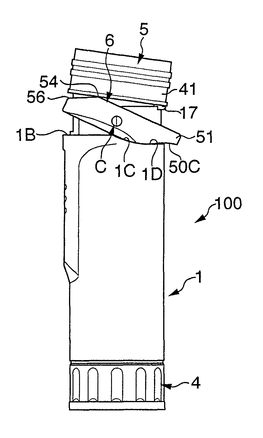
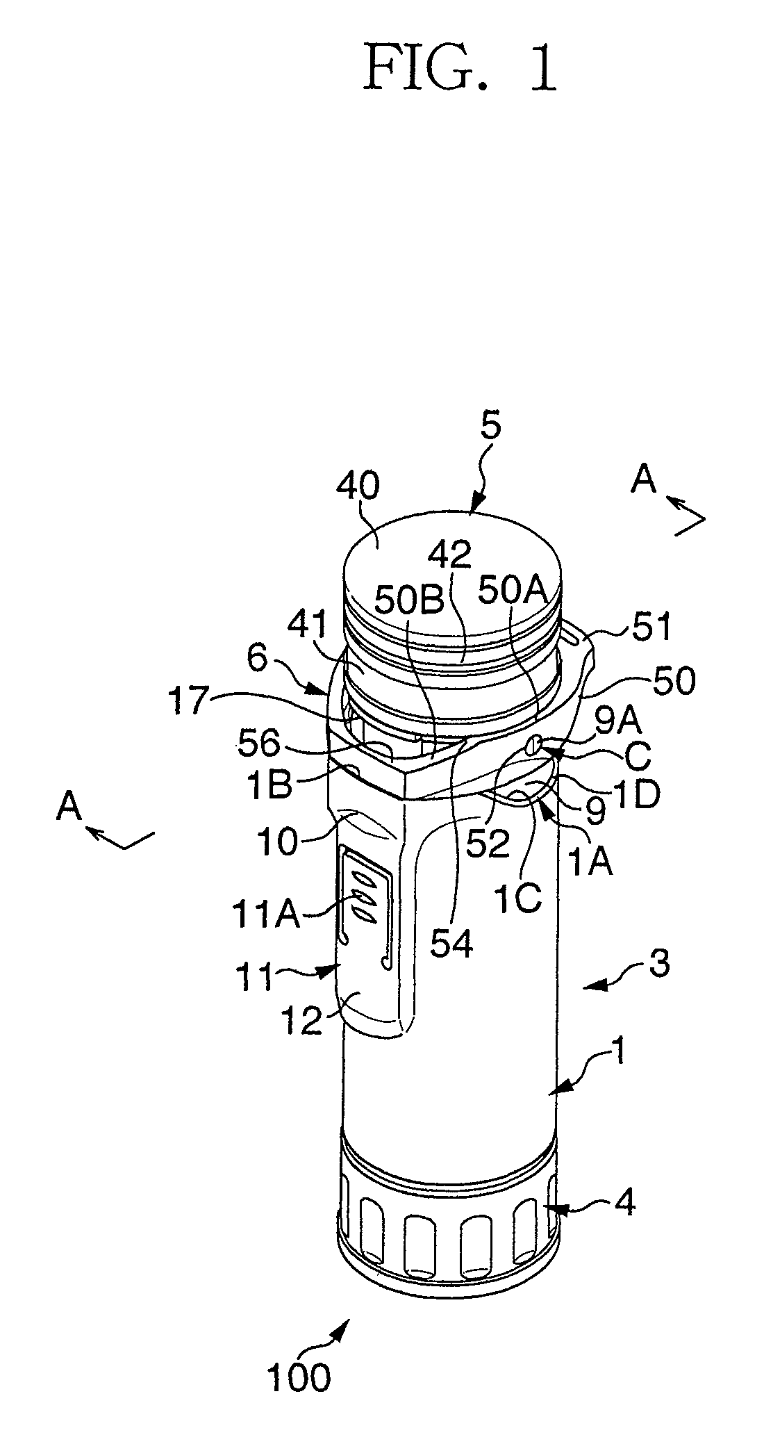
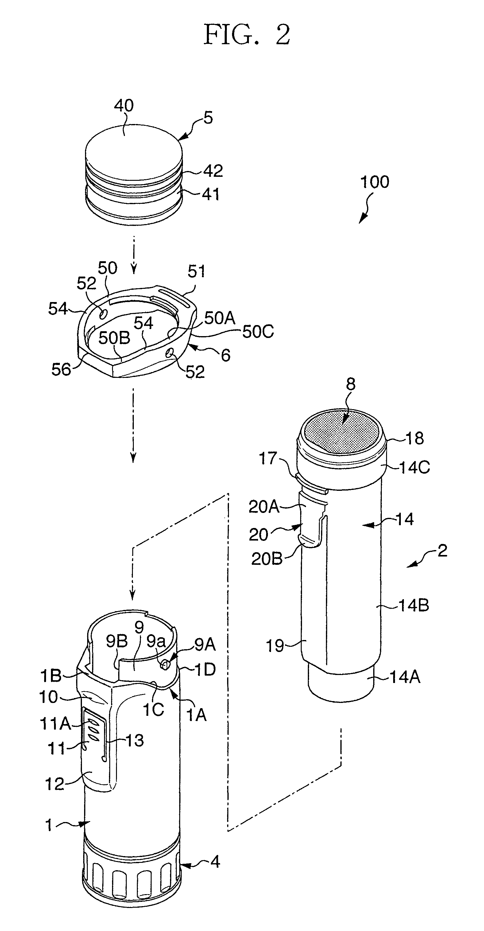
[0056]FIG. 1 is a schematic perspective view of a tubular case according to an embodiment of the present invention, and FIG. 2 is an exploded perspective view thereof. FIG. 3 is a schematic perspective view of the tubular case from which a cap is detached. Referring to these figures, a tubular case 100 comprises a case body 1, a case 3 including a cartridge 2, which is received in the case body 1 (refer to FIG. 2), an operating knob 4 rotatably attached to a lower end portion of the case body 1 in figures, a cap 5, engaging with an upper end portion of the cartridge 2 in figures, and an operating member 6 for releasing the engagement between the cap 5 and the cartridge 2.

[0057]As shown in FIG. 2, the external diameter in a specified area of the upper end of the ca...


PUM


Abstract

A cylindrical case receives a stick in a reciprocating manner so through an opening of the case. A cap is arranged to engage with the opening of the case. Engagement release of the cap is carried out by rotating an operating member. The operating member includes a peripheral member and an operating force imparting portion continuous with the peripheral member mounted on an upper portion of the case. When the operating force imparting portion is pressed downward, force apply points opposite to the operating force imparting portion impart a push-up force to the cap thereby releasing the cap from the engagement with the case.

Description

RELATED APPLICATIONS[0001]The present application is based on, and claims priority from, Japanese Application Ser. No. 2006-085442, filed Mar. 27, 2006, the disclosure of which is hereby incorporated by reference herein in its entirety.FIELD OF THE INVENTION[0002]The present invention relates to a tubular case arranged to receive, for example, a stick of solid glue as an item to be received in a reciprocating manner so as to come out and retract through an opening of the case, more particularly to a tubular case a cap of which can be easily detached from the case.BACKGROUND OF THE ART[0003]Conventionally, there is known a tubular case having a substantially cylindrical shape in appearance, which is arranged to receive a stick of solid glue as an item to be received in a reciprocating manner so as to come out and retract through an opening formed at one end of the case. The tubular case includes a cap covering the opening of the case. The cap is arranged to engage with the periphery ...

Claims


Application Information

Patent Timeline
Patent Type & Authority Patents(United States)
IPC IPC(8): B65D43/26B65D17/52B43M99/00
CPCB65D83/0011B43M11/00B65D83/00
Inventor KOBAYASHI, SHOGOSHIMA, HIDETO
Owner KOKUYO CO LTD
Why Eureka
Try Eureka