
Bicycle lighting apparatus

a technology for lighting apparatus and bicycles, applied in the field of bicycles, can solve the problems of adversely affecting the safety of riders, direct proportional light intensity, and computer-dependent battery-powered computers

Inactive Publication Date: 2007-03-20
SHIMANO INC
View PDF17 Cites 17 Cited by
  • Summary
  • Abstract
  • Description
  • Claims
  • Application Information

AI Technical Summary

Benefits of technology

[0010]In another embodiment, a bicycle lighting apparatus comprises a computer housing adapted to be mounted to a bicycle; a computer housed within the computer housing; a first lighting device housed within the computer housing for providing lighting outside of the computer housing, wherein the first lighting device is controlled by the computer; a second lighting device spaced apart from the computer housing; and electrical wiring connecting the second lighting device to the computer housing.
[0001]The present invention is directed to bicycles and, more particularly, to a bicycle lighting apparatus that may be used for illuminating bicycle components and / or the area around the bicycle.

Problems solved by technology

Unfortunately, such cycle computers usually are independently battery powered and are not adapted to interact with other bicycle components.
One problem with such lighting devices is that light intensity was directly proportional to the cycling speed.
Thus, there was no illumination unless the bicycle was moving, which adversely affected the rider's safety.
Also, the dynamo added resistance to wheel rotation, thus requiring additional pedalling effort by the rider.
However, if the cyclist fails to thoroughly charge the battery, the lighting device may fail at an undesirable time.
The device is battery powered, so the function of the cycle computer, the lighting device and / or the cellular phone is limited accordingly.
Furthermore, the disclosed device is nothing more than a mechanical combination of three independent devices in a common casing.
In any event, there is no flexibility in the lighting functions of any of the known devices.

Method used


Image

  • Bicycle lighting apparatus
  • Bicycle lighting apparatus
  • Bicycle lighting apparatus

Examples


Embodiment Construction

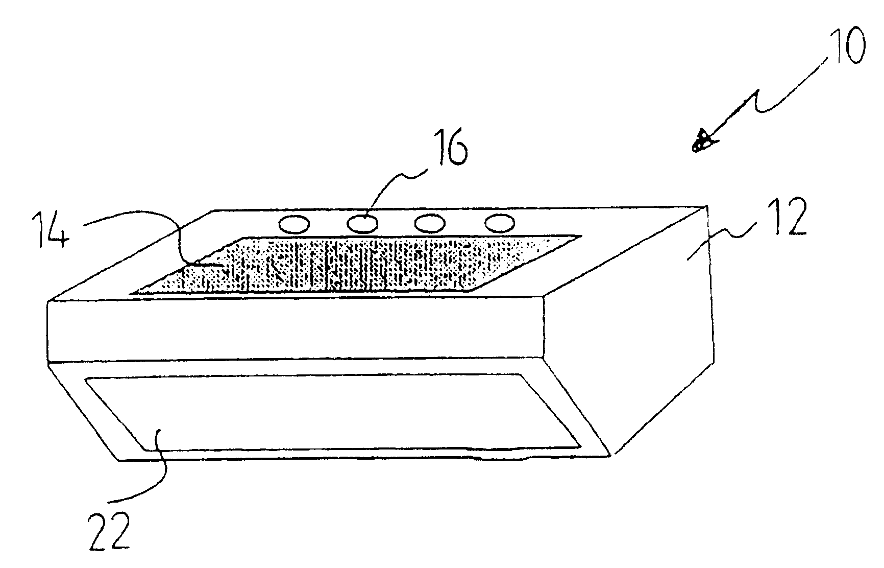
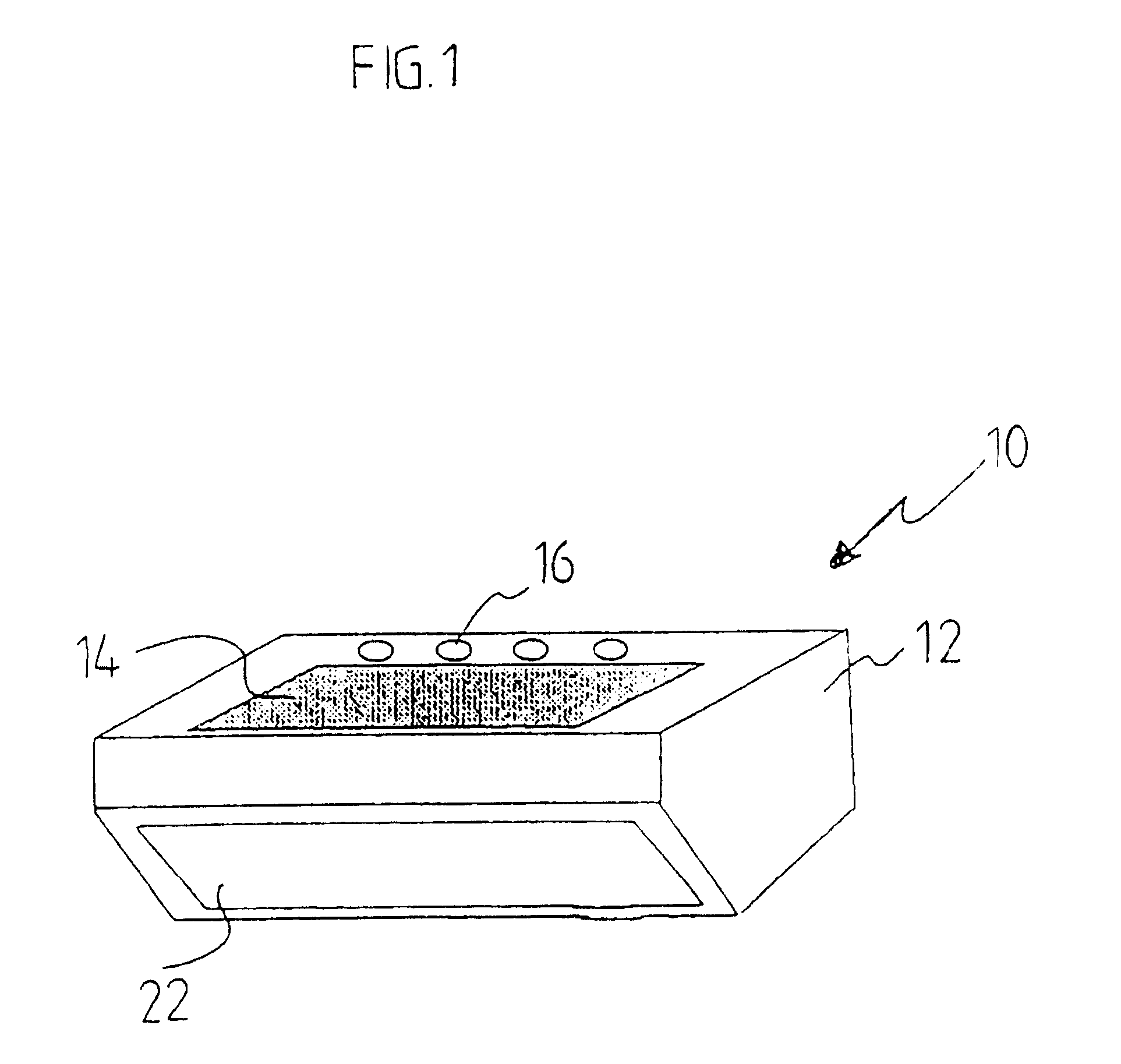
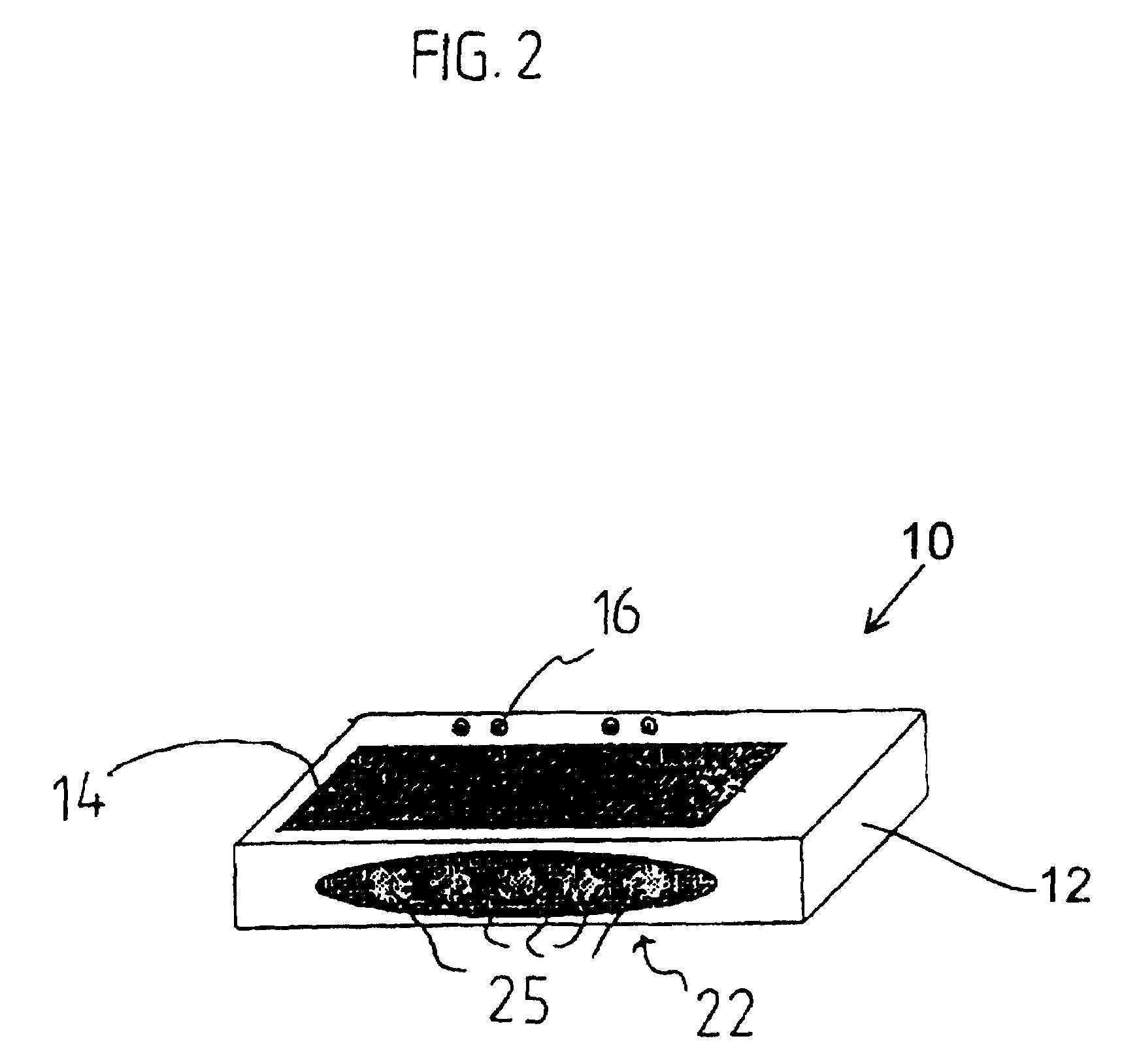
[0020]FIG. 1 shows a particular embodiment of a cycle computer 10 with an integrated lighting device 22. The cycle computer 10 comprises a computer housing 12 with a display 14 on the upper surface and switch elements 16 for controlling the operation of the cycle computer 10. The front of the computer housing 12 has a bevelled or inclined portion in which a lighting device 22 for lighting the road or some other area outside of the computer housing 12 is mounted. In this embodiment, the lighting device 22 comprises a light bulb (not shown) behind a translucent window element. If desired, the light emitted by the light bulb also may be directed upwardly to provide back lighting of the display 14 to reduce cost and the number of parts. The lighting device 22 and display 14 are housed together with a computer 32 (FIGS. 7 and 8) in the common housing 12, and the components are functionally coupled to each other and may receive signals from an internal hub dynamo 7 via wiring 8 (FIG. 3). ...


PUM


Abstract

A bicycle lighting apparatus comprises a computer housing adapted to be mounted to a bicycle, a computer housed within the computer housing, and an integrated lighting device that is controlled by the computer.

Description

BACKGROUND OF INVENTION[0001]The present invention is directed to bicycles and, more particularly, to a bicycle lighting apparatus that may be used for illuminating bicycle components and / or the area around the bicycle.[0002]Cycle computers and lighting devices often are provided as independent add-on features for bicycles. Cycle computers usually are detachably mounted on the bicycle handlebar, wherein the cycle computer gathers and displays information related to bicycle speed, cadence, distance travelled, and the like. For example, a magnet may be mounted to a wheel spoke or to some other rotating element, and a magnet sensor may be mounted to sense each passing of the magnet and provide corresponding electrical pulses. The electrical pulses can be used to calculate various parameters that are displayed to the cyclist. Some modern cycle computers have been designed to display information related to the state of the bicycle transmission as well. Unfortunately, such cycle computers...

Claims


Application Information

Patent Timeline
Patent Type & Authority Patents(United States)
IPC IPC(8): B62J6/00B62J6/02B62J6/12B62J11/00B62J11/19B62J99/00
CPCB62J6/003B62J6/18B62J99/00Y10S362/80B62J2099/0026B62J2099/008B62J11/19B62J6/015B62J50/22
Inventor TAKEDA, KAZUHIRO
Owner SHIMANO INC
Learn More