Methods and apparatus for estimating optical insertion loss

a technology of optical insertion loss and method, applied in the direction of optics, optical elements, instruments, etc., can solve the problems of diminishing the glow of the non-opaque portion of the connector, and achieve the effects of less controllable test conditions, high precision and cost effectiveness, and rapid and accurate measurement and analysis

Active Publication Date: 2007-03-20
CORNING OPTICAL COMM LLC
View PDF6 Cites 27 Cited by
  • Summary
  • Abstract
  • Description
  • Claims
  • Application Information

AI Technical Summary

Benefits of technology

[0008]In one aspect, the present invention provides a method and apparatus for estimating insertion loss at a mechanical joining point between optical fibers, such as, but not limited to, a mechanical splice, a mechanical termination using a field-installable connector, or a pair of mated optical connectors. The method and apparatus includes utilizing a “visual fault locator” (VFL) or other light source to launch light energy into one of the optical fibers of the mechanical joining point, thereby causing a portion of the mechanical joining point to glow so that a change in optical power can be detected, collected and measured. A means for detecting and collecting the light energy is positioned about a non-opaque portion of the mechanical joining point, such as a non-opaque portion of a mechanical splice used to splice an optical fiber to an adjoining optical fiber, a non-opaque portion of a mechanical splice connector used to terminate an optical fiber to a connector, or a non-opaque portion of an optical connector used to mate an optical fiber to an opposing optical fiber. An initial reference optical power level is measured and recorded at the fiber joining point prior to joining the optical fibers (e.g., splicing the optical fibers, terminating the optical fiber into the mechanical splice connector, mating the optical fiber to another connectorized optical fiber). The optical fiber is joined, and a final optical power level is measured and recorded. The final optical power level is then compared to the reference optical power level to provide an estimate of the insertion loss at the mechanical joining point between the optical fibers.
[0011]In yet another aspect, the present invention provides a method and apparatus for estimating the insertion loss at a mechanical joining point between a field optical fiber and a UniCam® field-installable mechanical splice connector available from Corning Cable Systems of Hickory, N.C. The UniCam® connector has unique design features that enable a rapid, accurate and cost effective estimate of the insertion loss of the field optical fiber during the termination process, but prior to crimping the lead-in tube to the tight-buffered material or tubing surrounding the field optical fiber. A means for collecting light is used to measure optical power, which in turn is used to estimate the optical insertion loss at the mechanical joining point. Each UniCam® connector is manufactured and assembled in a factory controlled environment with a highly precise and polished end face such that the optical insertion loss of the end face is held within a specified tolerance. The optical insertion loss of the connector end face is measured at the factory to ensure that the polished condition of the end face and the position of the stub optical fiber are as specified. A field insertion loss measurement is taken at the mechanical joining point between the stub optical fiber of the field-installable connector and the field optical fiber. No change should occur between the reference optical power measurement and the terminated optical power measurement other than the insertion of the prepared (e.g., cleaved, cleaned, polished) field optical fiber into the field-installable connector. The factory-determined insertion loss at the connector end face is then added to the field-determined insertion loss at the mechanical joining point to verify an acceptable termination and total connecter insertion loss. The insertion loss at the connector end face determined in the factory is utilized as part of the total insertion loss of the field-installable connector rather than relying on an insertion loss measurement conducted in the field utilizing an unsuitable test jumper (either unknown quality or one that has been measured incorrectly) mated to the UniCam® connector under less controllable test conditions.

Problems solved by technology

Consequently, the glow from the non-opaque portion of the connector likewise diminishes.

Method used


Image

  • Methods and apparatus for estimating optical insertion loss
  • Methods and apparatus for estimating optical insertion loss
  • Methods and apparatus for estimating optical insertion loss

Examples


Embodiment Construction

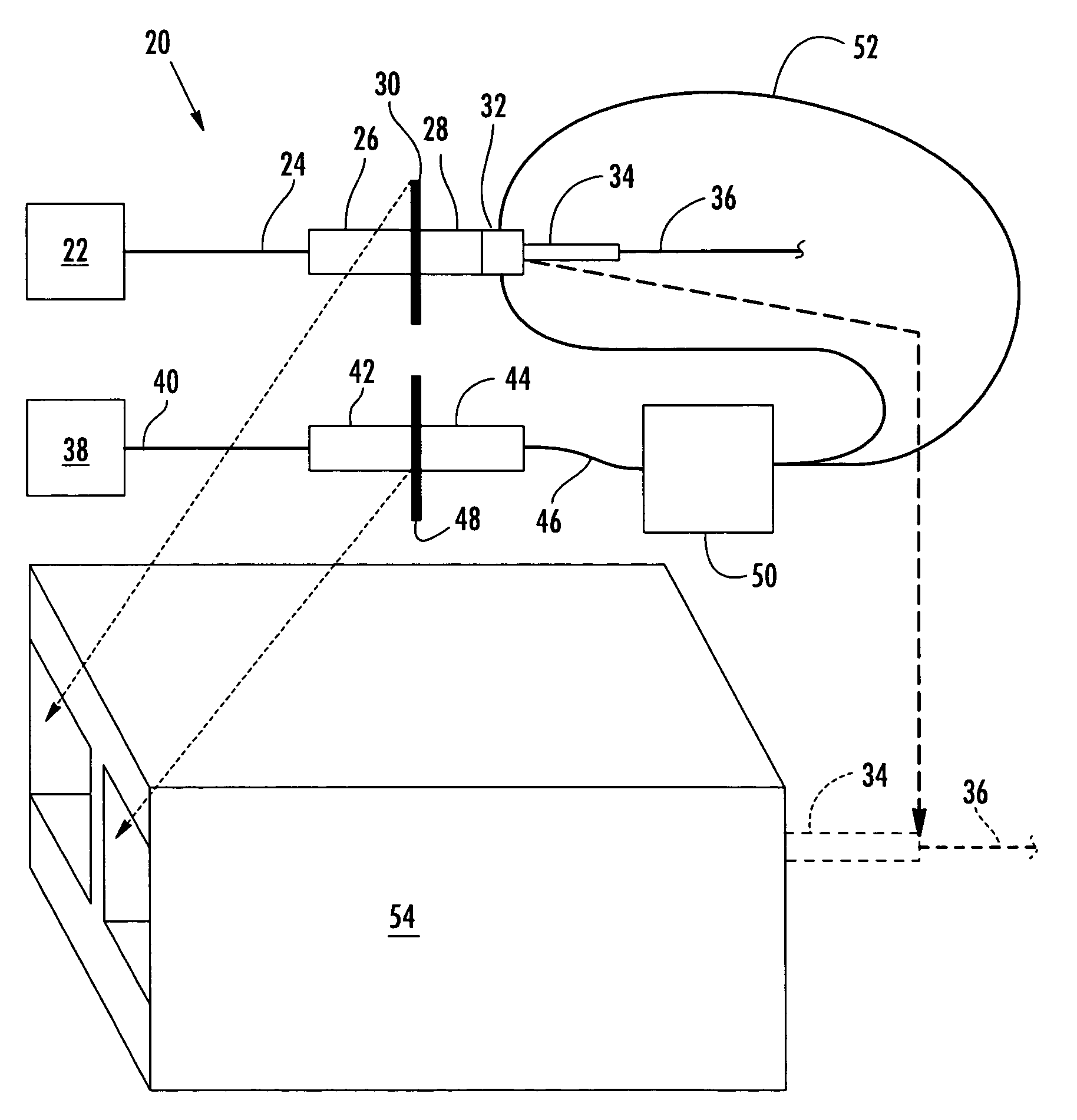
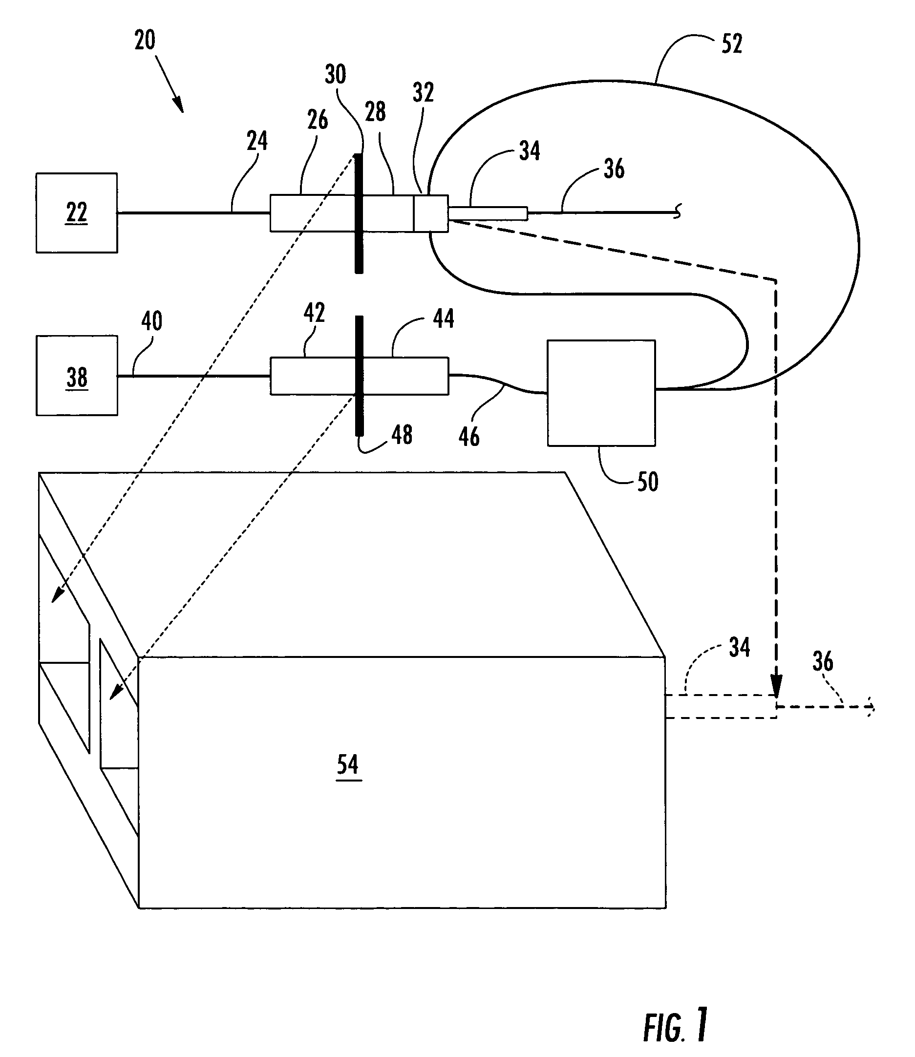
[0019]Reference will now be made in detail to the present preferred embodiments of the invention, examples of which are illustrated in the accompanying drawings. Whenever possible, the same reference numerals will be used throughout the drawings to refer to the same or like parts. A field-installable mechanical splice connector operable for terminating a field optical fiber to the connector is shown herein as an exemplary embodiment for estimating insertion loss at a mechanical joining point. However, it should be understood that the methods and apparatus of the present invention may be applied to any mechanical joining point, such as, but not limited to, any mechanical joining point between adjoining optical fibers wherein light energy can be transmitted along at least one of the optical fibers and the optical power at the mechanical joining point can be detected, collected and measured.

[0020]Referring to FIG. 1, the present invention provides a test apparatus 20 for estimating ins...


PUM


Abstract

A method for estimating insertion loss at a mechanical joining point between adjoining optical fibers includes introducing light energy into an optical fiber, using light collecting means to collect the light energy emanating from the optical fiber proximate the mechanical joining point, measuring a reference optical power prior to joining the optical fibers, measuring a terminated optical power after the optical fibers are joined, and comparing the terminated optical power to the reference optical power. An apparatus for estimating insertion loss includes a source of light for introducing light energy into an optical fiber, at least one optical fiber strand disposed about the mechanical joining point for collecting the light energy emanating from the optical fiber proximate the mechanical joining point, and an optical power meter coupled to the at least one optical fiber strand for measuring the optical power of the light energy emanating from the mechanical joining point.

Description

BACKGROUND OF THE INVENTION[0001]1. Field of the Invention[0002]The present invention relates generally to estimating optical insertion loss, and more particularly, to methods and apparatus for estimating insertion loss at a mechanical joining point between optical fibers.[0003]2. Technical Background[0004]Insertion loss at fiber joining points within an optical network should be determined to be within acceptable limits in order to verify proper physical contact between adjoining optical fibers and to maintain the system loss budget. Currently, one specified way of determining insertion loss is with the use of a hand-held optical loss test set, which measures the insertion loss through a length of optical fiber that may include one or more joining points between adjoining optical fibers. For example, a typical insertion loss measurement involves evaluating a length of optical fiber having a mated connector pair at each end of the optical fiber link being tested. However, the condit...

Claims


Application Information

Patent Timeline
Patent Type & Authority Patents(United States)
IPC IPC(8): G02B6/38
CPCG02B6/25G02B6/3806
Inventor TURNER, C. MARK
Owner CORNING OPTICAL COMM LLC
Why Eureka
Try Eureka