Information signal transmission system and remote control device for the same

a technology which is applied in the field of information signal transmission system and remote control device, can solve the problems of inability to start isochronous transmission and inability to perform band assignment, and achieve the effect of smooth switching

Inactive Publication Date: 2007-03-20
SATURN LICENSING LLC
View PDF22 Cites 96 Cited by
  • Summary
  • Abstract
  • Description
  • Claims
  • Application Information

AI Technical Summary

Benefits of technology

[0025]The remote control signal to which is added the identification code identifying the recipient of the information signal is transmitted; thus, the operation of the entire system is smoothly switched by allowing to provide the information signal the device that receives the remote control signal.

Problems solved by technology

When the overall capacity of the bands used in isochronous transmission exceeds the bus capacity, band assignment cannot be performed and isochronous transmission cannot be started.

Method used


Image

  • Information signal transmission system and remote control device for the same
  • Information signal transmission system and remote control device for the same
  • Information signal transmission system and remote control device for the same

Examples


first embodiment

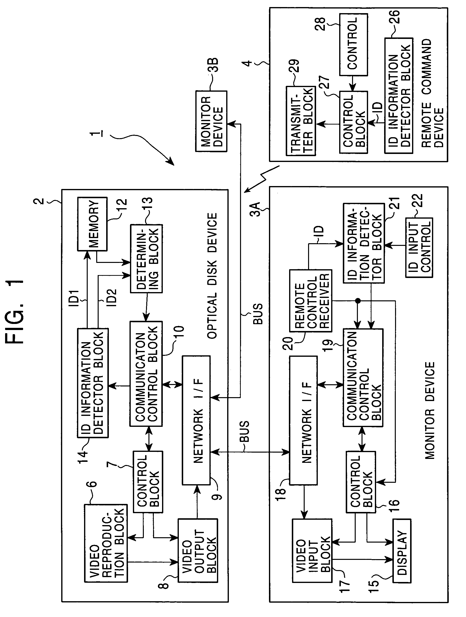
[0036]FIG. 1 is a block diagram showing an audio-visual (AV) system of a first embodiment of the present invention.

[0037]The AV system comprises an optical disk device 2, and monitor devices 3A and 3B which are connected through a bus BUS specified in IEEE1394 to form a network. The operation of the AV system 1 is switched by operating a remote command device 4 or by directly operating each device. The video signal and audio signal reproduced by the optical disk device 2 is monitored on the monitor device 3A in the same room as the optical disk device 2 or on the monitor device 3B in another room.

[0038]In the optical disk device 2, a video reproducing block 6 under the control of a control block 7 switches its operation to reproduce and output a video signal and audio signal from an optical disk. Under the control of the control block 7, the video output block 8 switches its operation to code output data of the video reproducing block 6 and provide its output to a network interface ...

second embodiment

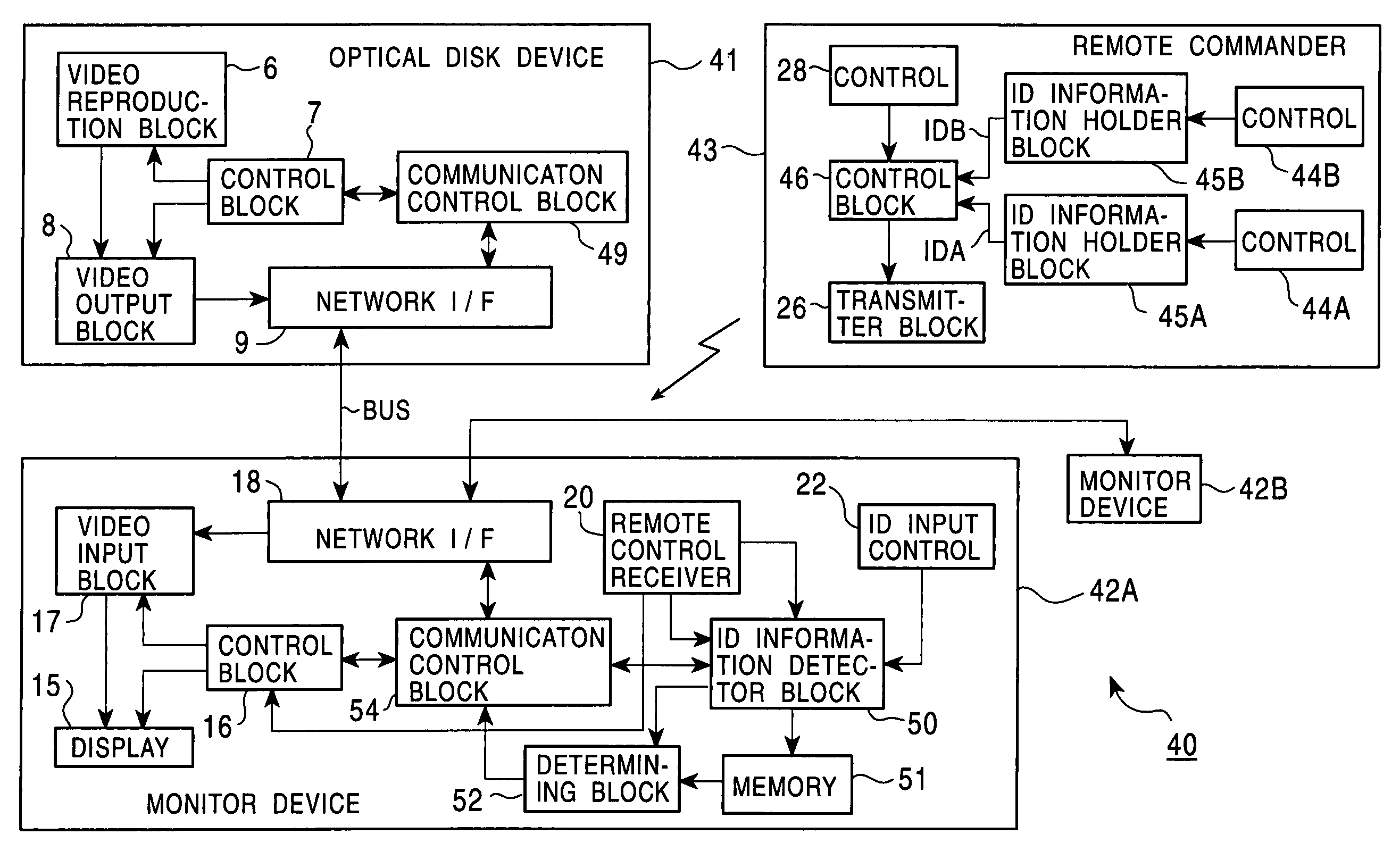
[0093]FIG. 8 is a block diagram showing an AV system of a second embodiment of the present invention.

[0094]The AV system 40 comprises an optical disk device 41, and monitor devices 42A and 42B which are connected through the bus BUS specified in IEEE1394 to form a network. The operation of the AV system 40 is switched by operating a remote command device 43 or by directly operating each device. In FIG. 8, components identical to those in the first embodiment with reference to FIG. 1 are designated with the same reference numerals, and the description about them is not repeated.

[0095]In the AV system 40, the remote command device 43 comprises ID input controls 44A, 44B, . . . , and in response of the operation of each of the ID input controls 44A, 44B, . . . , corresponding ID information holder blocks 45A, 45B, . . . send identification information IDA, IDB, . . . . The ID information holder blocks 45A, 45B, . . . are arranged into a memory and register a plural pieces of identifica...


PUM


Abstract

An information signal transmission system and a remote control device for such a system for allowing a viewer to continuously watch, for example, in a bedroom a program the viewer has watched in a living room. A recipient of information is detected referring to identification information set in a remote command device, and monitor devices are alternately switched for continuously providing the viewer with an information signal.

Description

BACKGROUND OF THE INVENTION[0001]1. Field of the Invention[0002]The present invention relates to an information signal transmission system and a remote control device for the information signal transmission system and finds applications in a system of video-handling devices that are interconnected using IEEE (the Institute of Electrical and Electronics Engineers) 1394, High Performance Serial Interface Bus Standard (hereinafter simply referred to as IEEE1394). The present invention detects a recipient of information, and provides continuous information signal by switching devices in accordance with the recipient of information. For example, a program that has been enjoyed by a viewer in a living room may be continuously enjoyed by the viewer in a bed room with a simple operation. The present invention enhances ease of use in this type of network.[0003]2. Description of the Related Art[0004]When a diversity of video-handling devices including a television tuner, a monitor device, and...

Claims


Application Information

Patent Timeline
Patent Type & Authority Patents(United States)
IPC IPC(8): H04N7/18H04N5/44H04N7/173G06F13/00H04L12/28H04N7/10
CPCH04L12/2805H04L12/282H04N21/43615H04N21/42204H04L12/2829H04N5/4403
Inventor NAKATA, JUNICHIWAKITA, YOSHIHIRO
Owner SATURN LICENSING LLC
Why Eureka
Try Eureka