Embroidery-frame mounting structure

a mounting structure and embroidery technology, applied in the field of embroidering frame mounting structure, can solve the problems of lowering the efficiency of embroidery operation, affecting the stitching efficiency and affecting the stitching accuracy of the embroidering fram

Inactive Publication Date: 2007-03-27
TOKAI IND SEWING MACH CO LTD
View PDF10 Cites 7 Cited by
  • Summary
  • Abstract
  • Description
  • Claims
  • Application Information

AI Technical Summary

Benefits of technology

[0013]In view of the foregoing, it is an object of the present invention to provide a technique which, when a mounting member is to be detached from a base frame, can minimize time and labor necessary for adjustment of a mounted position of the mounting member to thereby simplify the detachment / attachment of the mounting member and enhance the operational efficiency.
[0015]The base frame is driven relative to the tool (e.g., machine head) on the basis of embroidering data; for example, the base frame is driven in the X and Y directions substantially parallel to a table surface of an embroidery sewing machine. The base frame allows embroidery to be performed on an embroidering fabric, held on the embroidery frame, on the basis of the embroidering data. According to the present invention, the embroidery frame is removably secured to the mounting member, the positioning member is removably fixed to the base frame at a predetermined position, and the mounting member is mounted on the base frame via the positioning member. Also, the mounted position of the mounting member relative to the positioning member can be adjusted as desired. Namely, adjusting the position of the mounting member relative to the positioning member allows a mounted position of the base frame relative to the base frame to be set and adjusted as appropriate.
[0016]Thus, when the mounting member is to be removed from the base frame, it can be removed from the base frame along with the positioning member stilled secured to the mounting member. Thus, the mounting member can be removed from the base frame with its position relative to the positioning member and hence to the base frame of the embroidery frame still maintained. Because the positioning member is fixed to the base frame at a predetermined position, the mounting member can be mounted at the same position as before the removal, when the mounting member is to be again mounted on the base frame.). Therefore, once the position of the mounting member relative to the positioning member has been established, and when the mounting member is to be detached from the base frame, there is no need to repeat the mounted position adjustment of the embroidery frame (mounting member). As a consequence, the mounted position of the mounting member does not have to be re-adjusted each time the mounting member is removed from and again mounted on the base frame, which can thus eliminate the inconveniences that the embroidery sewing machine has to be kept in a halt state for a long time.

Problems solved by technology

However, if the embroidery frame is merely attached to the other embroidery sewing machine or laser processing machine, the sewing of the strand-like member or laser processing would be performed with undesired positional deviation relative to the already-embroidered pattern.
Thus, where the mounting members are to be temporarily dismounted from the base frame and then again mounted on the base frame, the operation for adjusting the mounted positions, relative to the base frame, of the mounting members has to be repeated, which tends to be very cumbersome.
Because the mounted position adjustment operation is very cumbersome and time-consuming, it would lead to a lowered efficiency of the embroidery operation.
Particularly, in the case where the embroidery sewing machine is provided with many (e.g., 20) machine heads, it would take much time and labor to adjust the mounted positions of the embroidery frames each time the mounting members are detached and reattached.
As a consequence, the conventional technique can only achieve poor productivity.

Method used


Image

  • Embroidery-frame mounting structure
  • Embroidery-frame mounting structure
  • Embroidery-frame mounting structure

Examples


Embodiment Construction

[0030]Embodiments of the present invention will now be described with reference to the accompanying drawings.

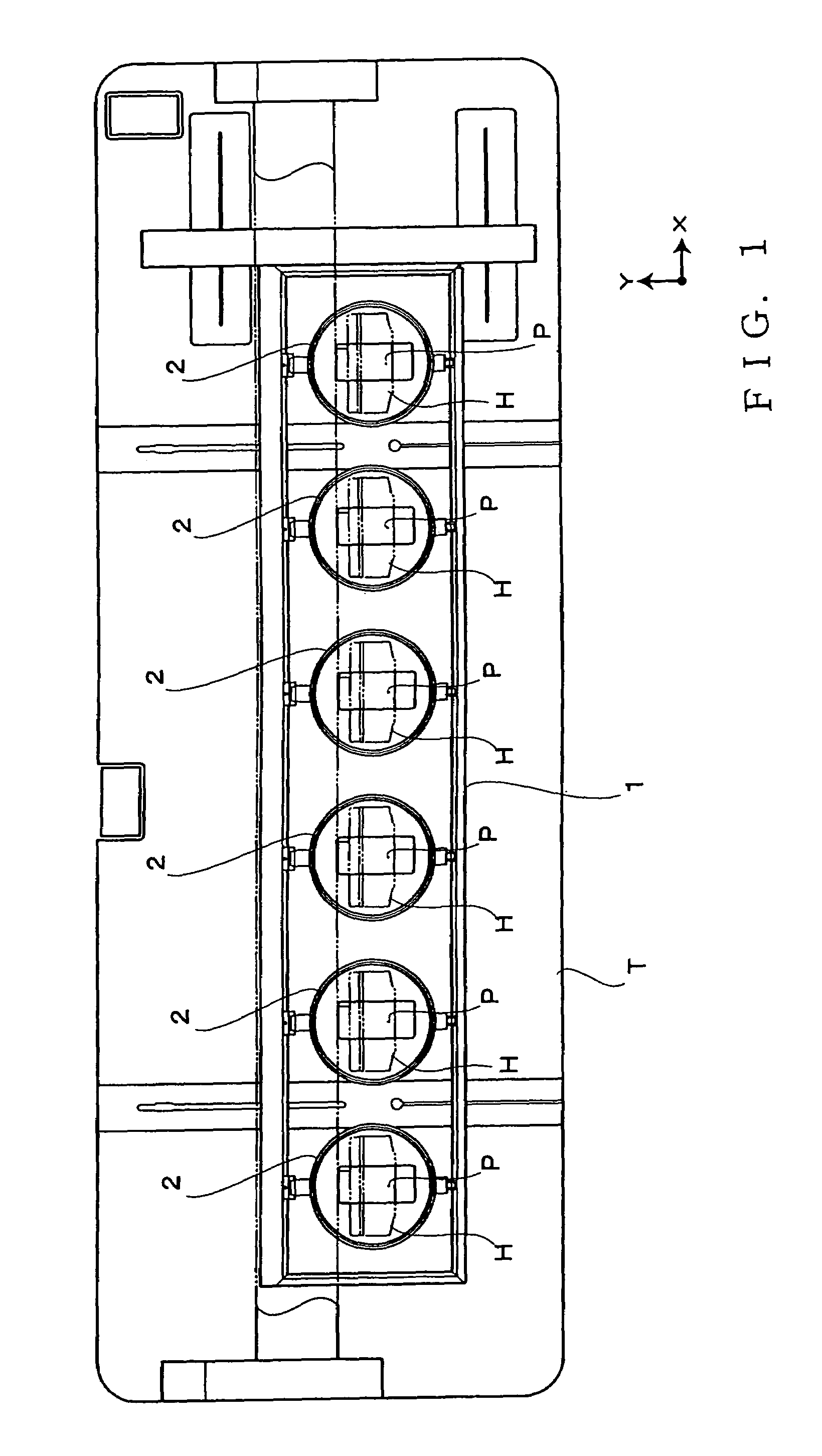
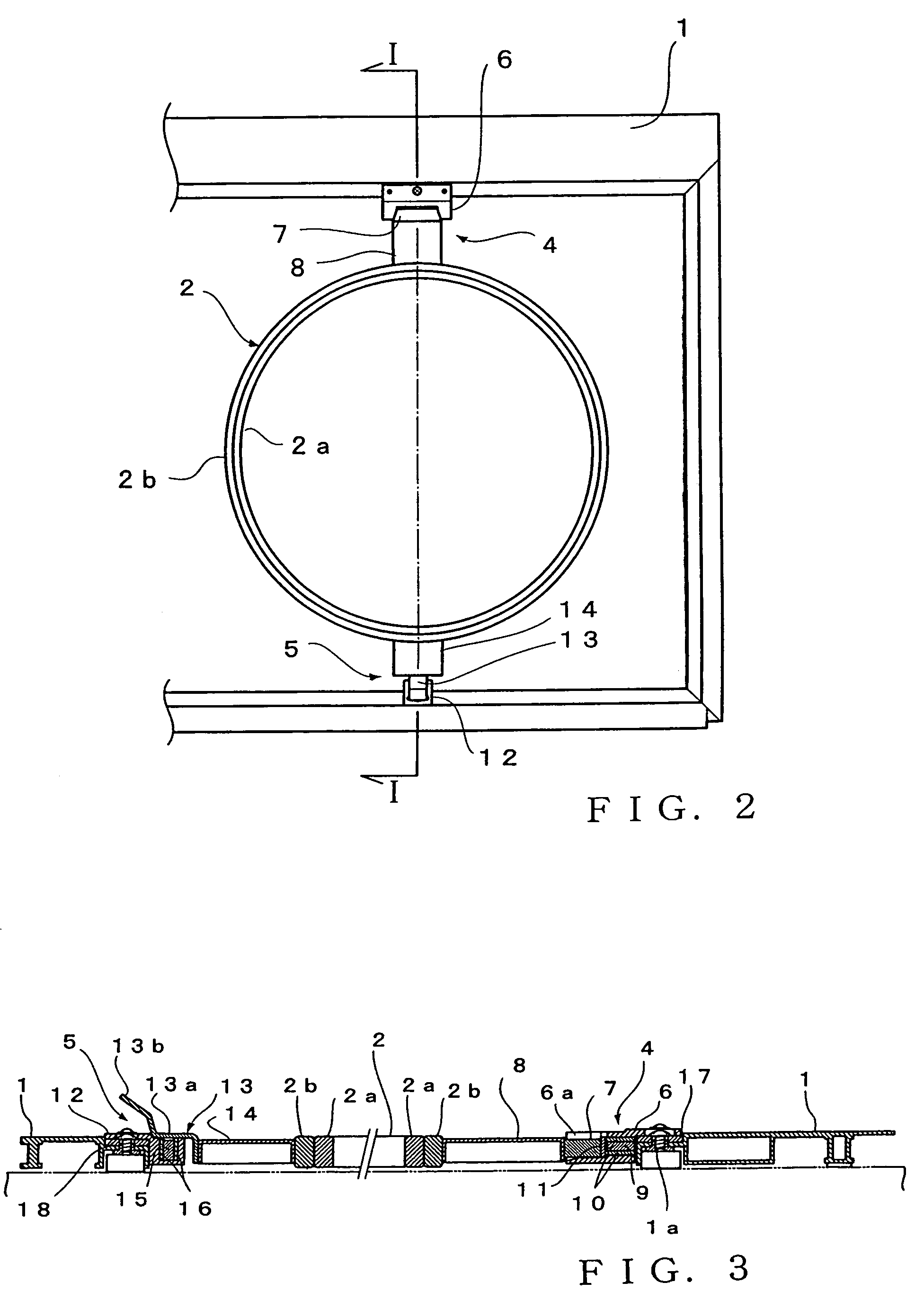
[0031]FIG. 1 is a plan view showing a general setup of a multi-head embroidery sewing machine, FIG. 2 is a plan view showing in enlarged scale one of embroidery frames 2, i.e. the rightmost embroidery frame in FIG. 1, and FIG. 3 is a sectional view taken along the I—I line of FIG. 2.

[0032]In FIG. 1, a base frame 1, having a rectangular shape as viewed in plan, is placed on a table T of the multi-head embroidery sewing machine that is provided with a plurality of machine heads (in the illustrated example, six machine heads) H. The base frame 1 is movable, via a not-shown X-axis drive mechanism and Y-axis drive mechanism, in the X-axis and Y-axis directions in substantially parallel to the surface of the table T. Six embroidery frames 2 are removably attached to the base frame 1 in corresponding relation to the six machine heads H. As seen in FIGS. 2 and 3, each of the embroide...


PUM


Abstract

An embroidery frame for holding an embroidering fabric in a spread-out condition is detachably attached to mounting members at a predetermined position. Positioning members are removably fixed to a base frame at a predetermined position. The mounting members are attached to the positioning members so that their mounted positions relative to the positioning members are adjustable, so that the embroidery frame is adjustably and removably mounted on the base frame via the mounting members and the positioning members. Once the position of the mounting members relative to the positioning members has been established, and when the mounting members are to be detached from the base frame, the mounting members only have to be detached together with the positioning members so that the relative positional relationship between the adjusted positional state of the mounting members relative to the positioning members can be maintained.

Description

[0001]This application is a U.S. National Phase Application of PCT International Application PCT / JP2004 / 009418 filed on Jul. 2, 2004 and claims priority from JP 2003-192150 filed on Jul. 4, 2003.TECHNICAL FIELD[0002]The present invention relates to an improvement in the structure for mounting an embroidery frame, holding an embroidering (i.e., to-be-embroidered) fabric or other embroidering workpiece, to a base frame driven on the basis of embroidering data.BACKGROUND ART[0003]There are a great variety of embroidered products, among which are known those made using a combination of embroidery and sewing of a strand-like member and using a combination of embroidery and laser processing. Examples of the known sewing machines for making such embroidered products include ones that are provided with an embroidery sewing machine head and a machine head capable of sewing a strand-like member, and ones that are provided with an embroidery sewing machine head and laser head capable of laser ...

Claims


Application Information

Patent Timeline
Patent Type & Authority Patents(United States)
IPC IPC(8): D05C9/04D05C9/00D05B39/00
CPCD05C9/04
Inventor TAJIMA, IKUOMURASE, AISUKE
Owner TOKAI IND SEWING MACH CO LTD
Why Eureka
Try Eureka