Method of measuring flatness of chamfering table

a technology of chamfering table and flatness, which is applied in the direction of measuring tapes, manufacturing tools, instruments, etc., can solve the problem of dangerous operation of directly measuring achieve the effect of monitoring the flatness minimizing labor and time loss, and reducing the degree of deterioration of the chamfering tabl

Active Publication Date: 2016-04-12
SAMSUNG CORNING PRECISION MATERIALS CO LTD
View PDF10 Cites 1 Cited by
  • Summary
  • Abstract
  • Description
  • Claims
  • Application Information

AI Technical Summary

Benefits of technology

[0011]According to embodiments of the present invention, it is possible to monitor the flatness of the chamfering table and express the result in quantized values. In particular, the present invention makes it possible to promptly determine the degree of deterioration of the chamfering table which is continuously deteriorated by the repeated chamfering operation, and to directly take necessary measures. This has an advantage of being capable of minimizing labor and time loss, thereby improving the efficiency of the chamfering operation. In particular, the present invention can automate the operation of measuring the flatness, thereby removing the load of the operation pertaining to measurement.
[0012]In addition, according to embodiments of the present invention, it is possible to indirectly measure the flatness of the chamfering table instead of directly measuring it. The operation of directly measuring the flatness of the chamfering table is a dangerous operation which must be carried in the middle of equipment after the production line is momentarily stopped. The present invention can minimize the time for which the equipment stays stopped (a time required for machining about 10 substrates: 5 minutes) and protect a worker from a dangerous environment.
[0014]In addition, when separate measuring equipment is used, a measurement error may occur since a measuring point by the measuring equipment may be misaligned from an actual point that is chamfered by the chamfering wheel. In contrast, the present invention can prevent such a measurement error by defining the flatness with respect to the chamfering wheel.

Problems solved by technology

The operation of directly measuring the flatness of the chamfering table is a dangerous operation which must be carried in the middle of equipment after the production line is momentarily stopped.

Method used


Image

  • Method of measuring flatness of chamfering table
  • Method of measuring flatness of chamfering table
  • Method of measuring flatness of chamfering table

Examples


Embodiment Construction

[0020]Reference will now be made in detail to various embodiments of the present invention, examples of which are illustrated in the accompanying drawings and described below, so that a person having ordinary skill in the art to which the present invention relates can easily put the present invention into practice.

[0021]Throughout this document, reference should be made to the drawings, in which the same reference numerals and signs are used throughout the different drawings to designate the same or similar components. In the following description of the present invention, detailed descriptions of known functions and components incorporated herein will be omitted when they may make the subject matter of the present invention unclear.

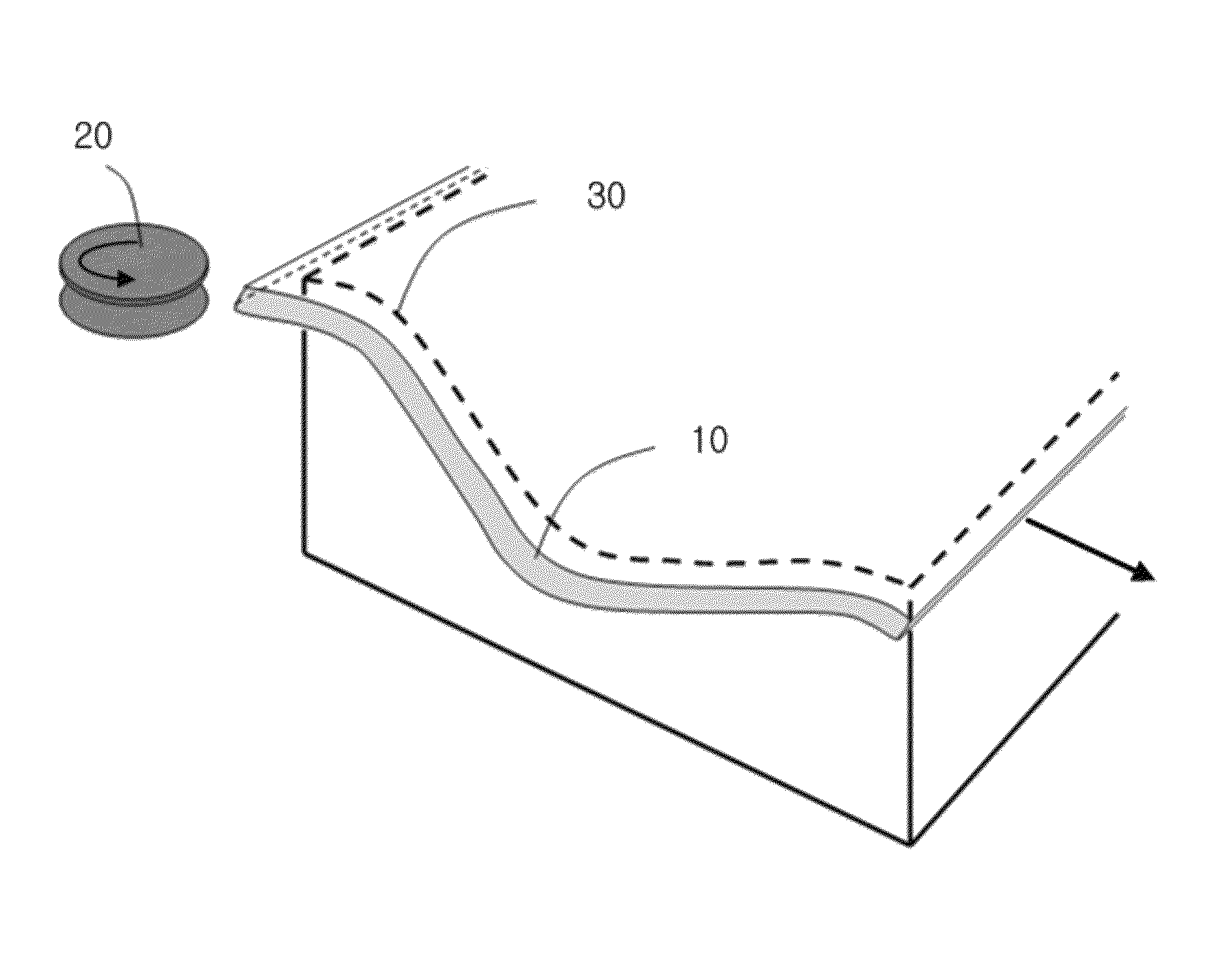
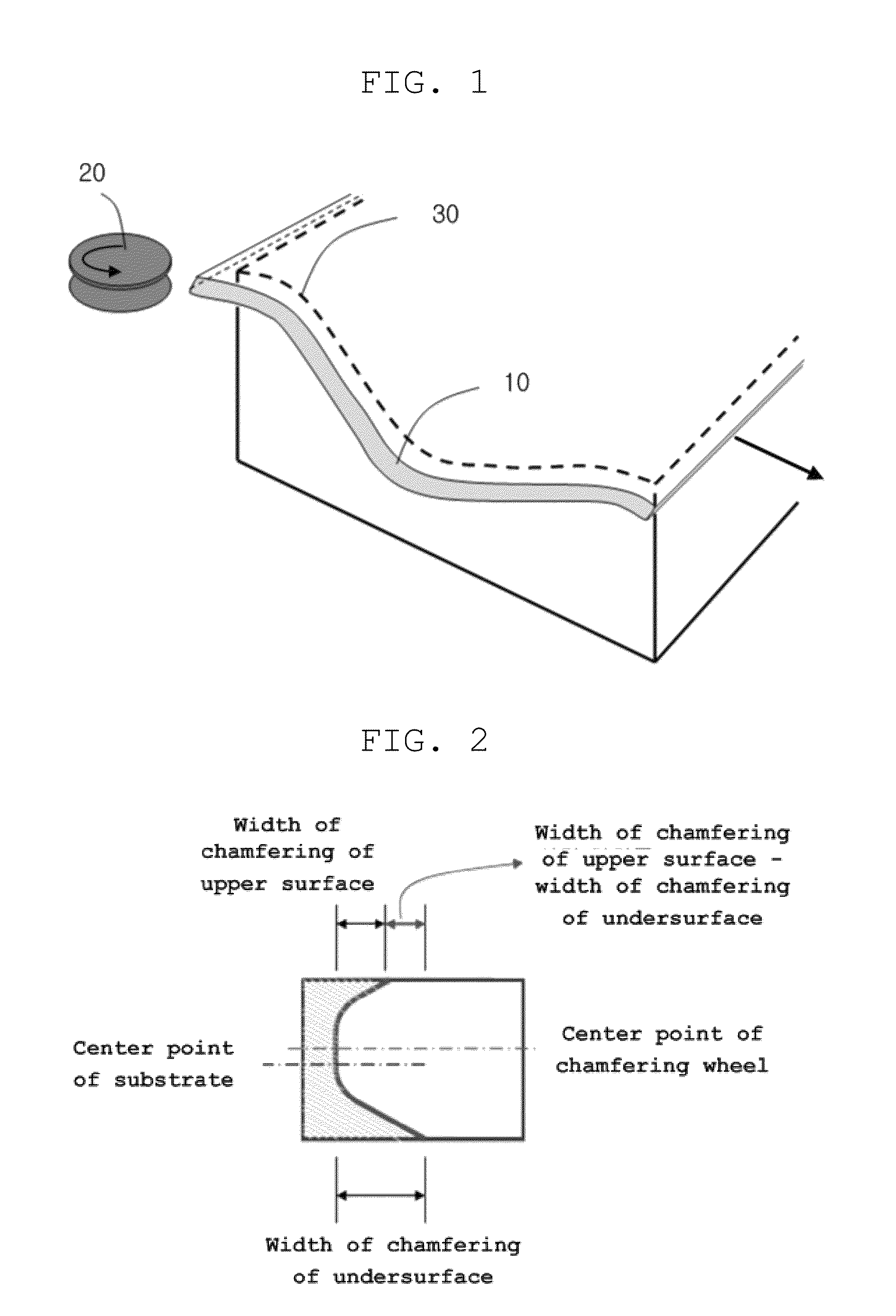
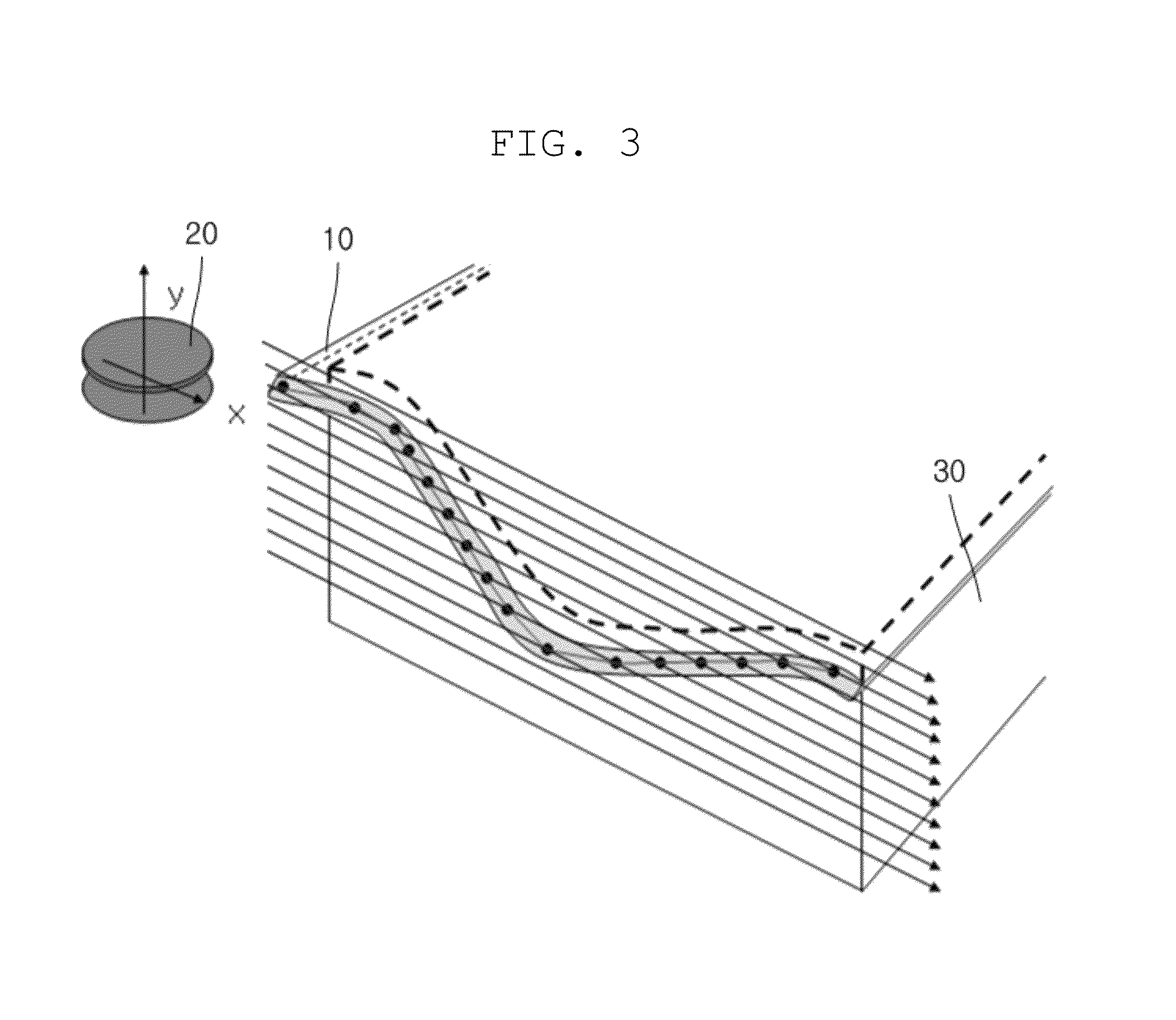
[0022]FIG. 1 is a schematic view showing the operation of chamfering one edge of a substrate.

[0023]The substrate 10 is placed on a chamfering table 30. Herein, the terms “up (upward),”“down (downward),”“left” and “right” are used to describe the position...


PUM


Abstract

A method of measuring a flatness of a chamfering table includes the steps of positioning a substrate on the chamfering table, chamfering an edge of the substrate a plurality of times with a chamfering wheel while varying a relative height of the chamfering wheel with respect to a height of the substrate, locating symmetric chamfered points where the chamfered edge is top-bottom symmetric, matching values of the relative height of the chamfering wheel to the found symmetric chamfered points, and obtaining the flatness of the chamfering table from the values of the relative height of the chamfering wheel that are matched to the symmetric chamfered points.

Description

CROSS REFERENCE TO RELATED APPLICATION[0001]The present application claims priority from Korean Patent Application Number 10-2013-0060440 filed on May 28, 2013, the entire contents of which are incorporated herein for all purposes by this reference.BACKGROUND OF THE INVENTION[0002]1. Field of the Invention[0003]The present invention relates to a method of measuring the flatness of a chamfering table, and more particularly, to a method of measuring the flatness of a chamfering table, in which the flatness of the chamfering table can be provided as a quantized result.[0004]2. Description of Related Art[0005]In a plurality of fields, the edges of substrates are required to be chamfered. For instance, glass substrates which are used for flat panel displays, such as a liquid crystal display (LCD), a plasma display panel (PDP) and an electroluminescent display (ELD), can be manufactured by melting, shaping, cutting and chamfering processes. That is, it is possible to manufacture a glass s...

Claims


Application Information

Patent Timeline
Patent Type & Authority Patents(United States)
IPC IPC(8): G01B5/20G01B3/10
CPCG01B3/1084G01B5/20G01B2003/1094G01B3/1094B24B9/06G01B21/20
Inventor HAN, MYEONGBO
Owner SAMSUNG CORNING PRECISION MATERIALS CO LTD
Why Eureka
Try Eureka