Dental sensor clamp

a technology of dental sensors and clamps, applied in the field of dental clamps, can solve the problems of difficult patient comfort, difficult use, and large volume of digital sensors in the patient's mouth, and achieve the effects of convenient use, reliable sterilization, and high quality

Active Publication Date: 2007-03-27
KERRHAWE
View PDF20 Cites 24 Cited by
  • Summary
  • Abstract
  • Description
  • Claims
  • Application Information

AI Technical Summary

Benefits of technology

[0009]The present invention provides dental sensor clamps that locate and secure sensors of different sizes such that full and high quality images of the periapical area of the anterior and posterior teeth are provided. The dental sensor clamps of the present invention are easy to use and provide consistent positioning of the sensors near the apical area of the teeth. The dental sensor clamps of the present invention provide high quality images with a minimum of artifacts and shadows, can be reliably sterilized between uses, are more comfortable for patients and are especially useful in endodontics.
[0011]In an alternative embodiment, the dental sensor clamp body has a first portion at the one end connectable to a bite plate and a second portion between the ends of the clamp body. The clamp slide is located within a thickness of the second portion, thereby providing a relatively thin clamp body, which facilitates obtaining optimal images from the sensor.
[0012]In a further embodiment, the clamp body has a slot extending longitudinally in the clamp body. Tabs extend from opposite walls of the slot, and the clamp slide is located in the slot and between the tabs to be movable toward and away from the fixed stop. This open structure, with no cover plate over the clamp slide, permits reliable sterilization between uses.

Problems solved by technology

In contrast, digital sensors do not have standard dimensions and are often relatively large and bulky and are often connected to an electrical cable; and thus, the handling of digital sensors in the patient's mouth is somewhat problematic and often uncomfortable for the patient.
There are also known holders that can accommodate digital imaging sensors of different sizes; however, commercially available holders have several disadvantages.
In either event, valuable time in the dental suite is lost with a further penalty of additional patient discomfort and irritation.
Further, portions of the sensor clamp often overlay an imaging field of the sensor, and those sensor clamp portions can appear as artifacts or shadows in the resulting image.
Further, with active structures, additional artifacts or shadows can be caused by movable parts of active structures that present different thicknesses in the imaging field.
Such enclosed volumes present barriers to the flow of steam or other sterilizing fluid and are difficult to completely sterilize between uses.
However, if the sensor is not carefully located and tightly secured between the arms, the sensor may experience motion, which often adversely affects the quality of the presentation of the resultant image.

Method used


Image

  • Dental sensor clamp
  • Dental sensor clamp
  • Dental sensor clamp

Examples


Embodiment Construction

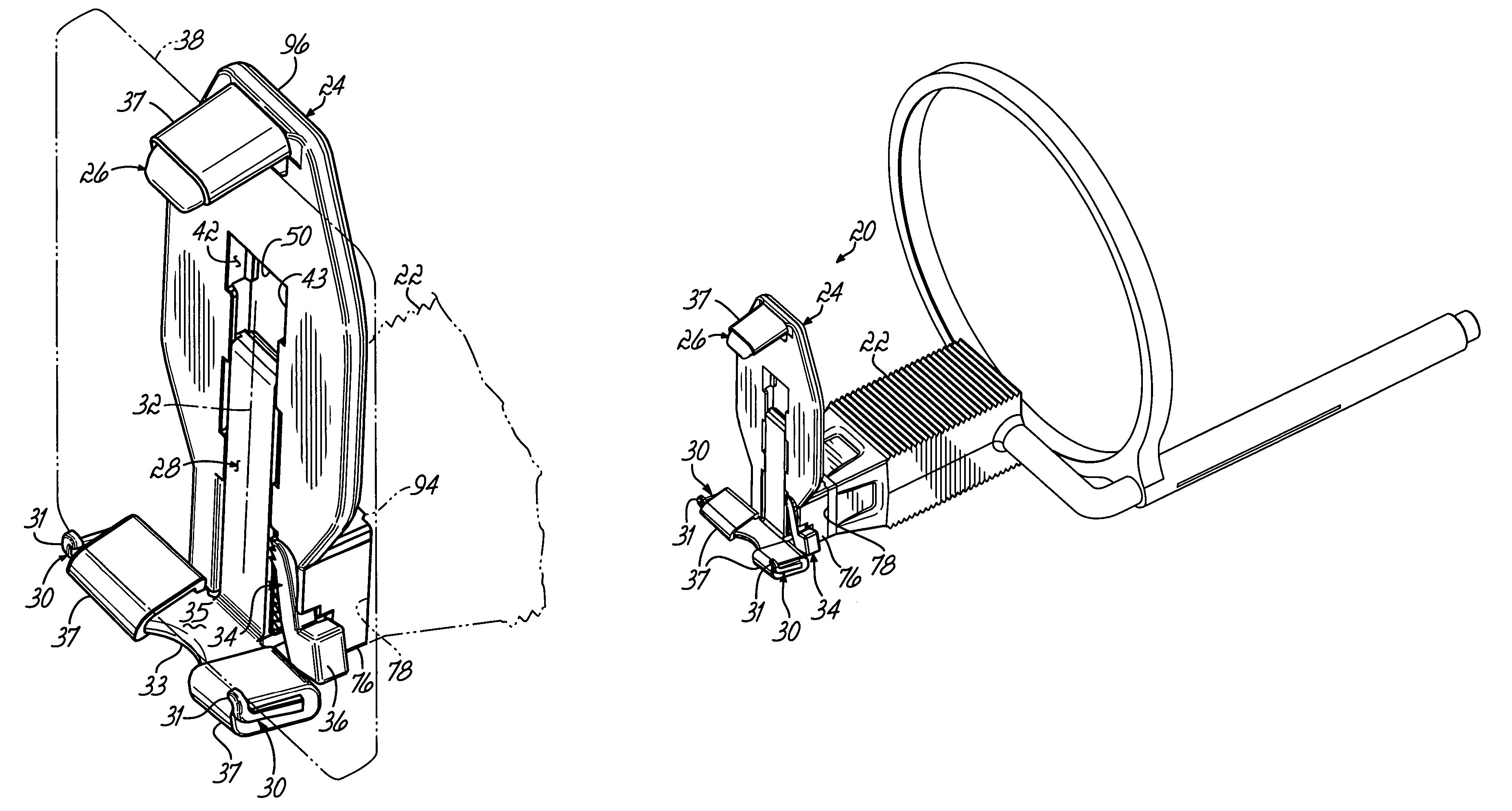
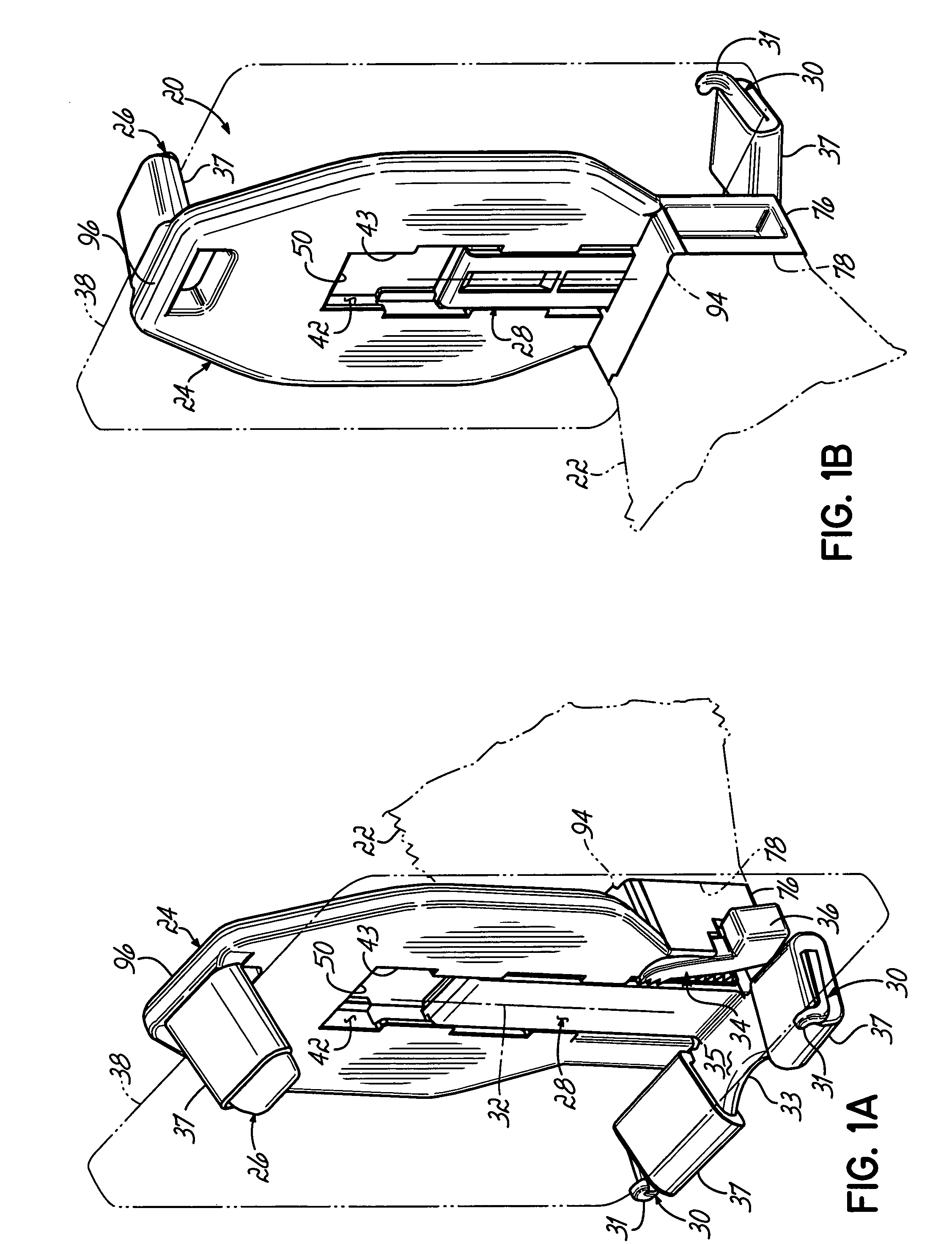
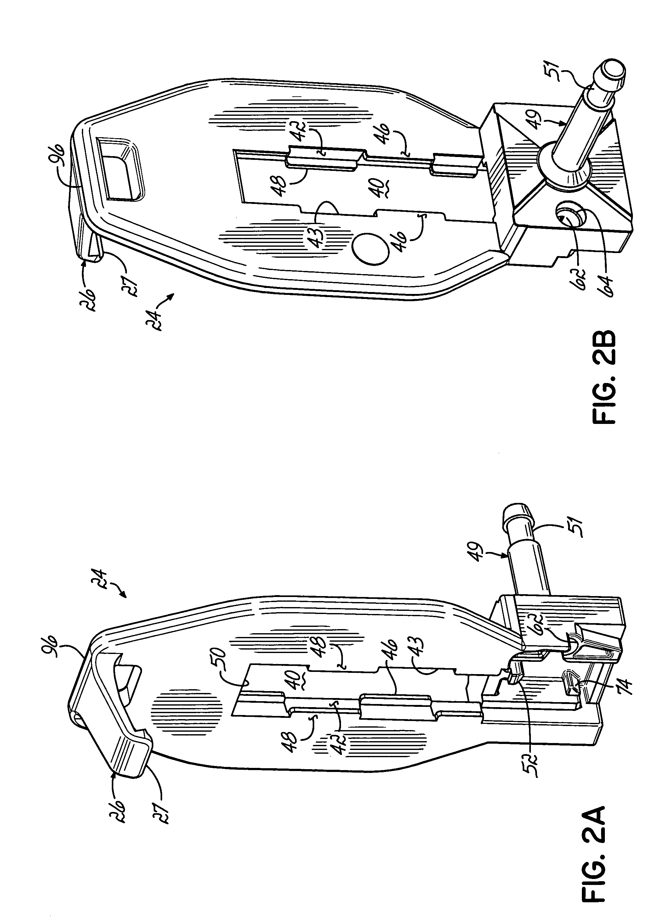
[0027]Referring to FIGS. 1A and 1B, an anterior sensor clamp 20 is attachable to an anterior bite plate 22 shown in phantom. The anterior sensor clamp 20 has an anterior clamp body 24 with an upper fixed stop 26. A clamp slide 28 is mounted for sliding movement in the clamp body 24, and the clamp slide 28 has a pair of resilient clamping arms 30 that extend in opposite directions from a clamp slide centerline 32. The fixed stop 26 and resilient arms 30 are covered by a soft, compliant material 37, for example, rubber pads, which are compatible with, and do not damage, a hygienic pouch or other protective envelope that is placed over the sensor during use.

[0028]To open the sensor clamp 20, a pivotable anterior release arm 34 is moved out of locking engagement with the clamp slide 28 by pushing a release button 36 formed on an outer end of the release arm 34. With the release button 36 depressed, the clamp slide 28 is movable or slidable with respect to the clamp body 24 in a generall...


PUM


Abstract

A dental sensor clamp has a clamp body with a connector on one end for connecting the sensor clamp to a bite plate. A clamp body opposite end has a fixed stop locatable adjacent an apical area of a tooth. A clamping slide is mounted within a thickness of the clamp body, and the clamping slide supports a member providing a resilient clamping force upon the member being moved against the sensor and the fixed stop. The dental sensor clamp reliably secures an imaging sensor adjacent the apical area of the tooth.

Description

FIELD OF THE INVENTION[0001]The present invention relates generally to dentistry and, more particularly, to a dental clamp for a sensor.BACKGROUND OF THE INVENTION[0002]It is known to generate images of a patient's teeth in order to determine their state of health as well as to diagnose and treat diseases. Further, for the treatment of diseases or injuries that affect the root tip or nerve of the tooth, an image or other presentation of the periapical area of the teeth is most desirable. As used herein, “an image or other presentation of the periapical area of the teeth” means an image or other presentation that shows the whole tooth both above and below the gum line. Such images and presentations include radiographs recorded on X-ray film and images provided by a digital image sensor.[0003]Digital images are captured by either digital imaging plates located within the patient's mouth or a digital imaging sensor that provides a signal via a cable or wireless transmission to a comput...

Claims


Application Information

Patent Timeline
Patent Type & Authority Patents(United States)
IPC IPC(8): A61B6/14G03B42/04
CPCG03B42/042A61B6/145A61B6/4423
Inventor QUARRY, ANTONYKILCHER, BEATDA ROLD, MARCOKLAUSER, ROLF M.
Owner KERRHAWE
Why Eureka
Try Eureka