Thermopile temperature sensing with color contouring

a temperature sensing and thermometer technology, applied in the field of thermometer temperature sensing with color contouring, can solve the problem that the ability to provide temperature information is limited to the field of view of the particular devi

Inactive Publication Date: 2007-03-27
AVAGO TECH ECBU IP (SINGAPORE) PTE LTD
View PDF17 Cites 48 Cited by
  • Summary
  • Abstract
  • Description
  • Claims
  • Application Information

AI Technical Summary

Problems solved by technology

While thermopile sensors work well to detect the temperature of an object, their ability to provide temperature information is limited to the field of view of the particular device.

Method used


Image

  • Thermopile temperature sensing with color contouring
  • Thermopile temperature sensing with color contouring
  • Thermopile temperature sensing with color contouring

Examples


Embodiment Construction

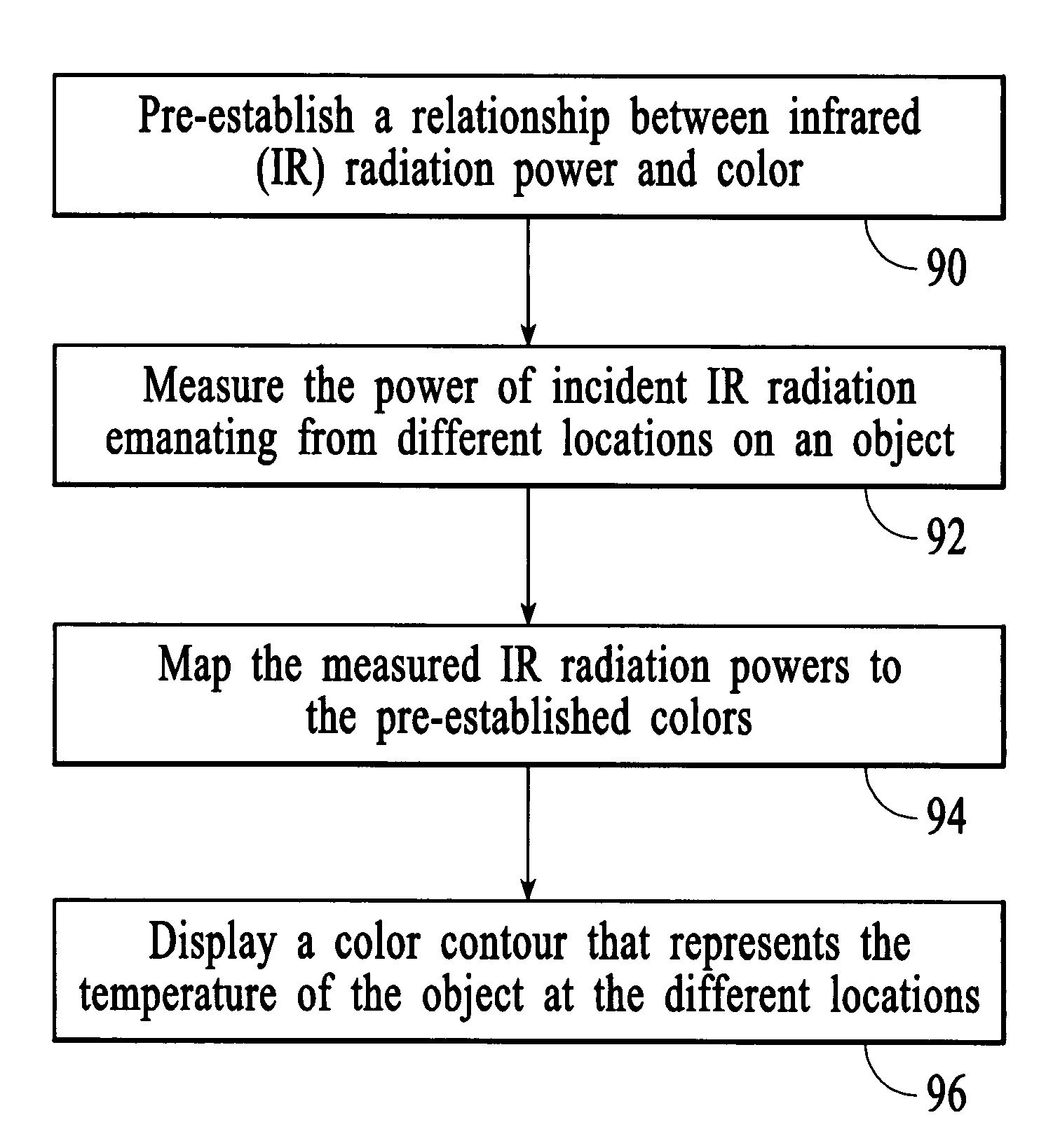
[0020]A color contour of an object is displayed from information that is obtained using an array of thermopile sensors. A color contour of an object is generated by pre-establishing a relationship between IR radiation power and color, measuring the power of incident IR radiation emanating from different locations on the object, mapping the measured IR radiation powers to colors, and generating color contour information that can be displayed on a color display. The color contour information represents the temperature of an object at different locations.

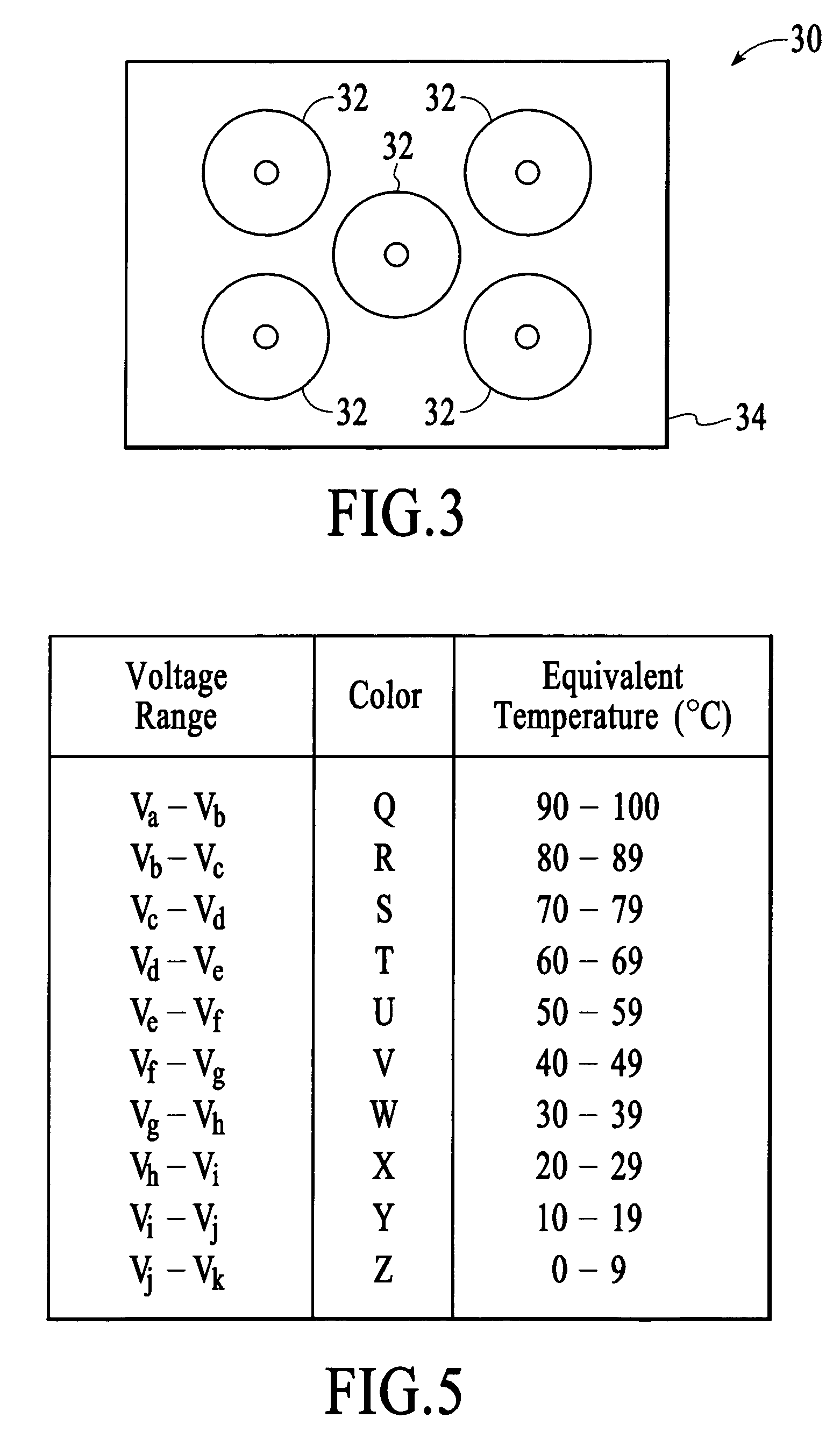
[0021]FIG. 3 depicts an array 30 of thermopile sensors 32 that is used to generate a color contour. The thermopile sensors in the array are configured such that the fields of view of the individual thermopile sensors combine to form a larger field of view. In the embodiment of FIG. 3, the thermopile sensors are individually packaged thermopile sensors that are connected together into a sensor array structure 34. Although the thermopile...


PUM

PropertyMeasurementUnit
temperatureaaaaaaaaaa

Abstract

A color contour of an object is displayed from information that is obtained using an array of thermopile sensors. A color contour of an object is generated by pre-establishing a relationship between IR radiation power and color, measuring the power of incident IR radiation emanating from different locations on the object, mapping the measured IR radiation powers to colors, and generating color contour information that can be displayed on a color display. The color contour information represents the temperature of an object at different locations.

Description

BACKGROUND OF THE INVENTION[0001]Thermopile sensors produce a voltage that is proportional to the power of the incident infrared (IR) radiation. Because all objects emit IR radiation, a thermopile can be used to measure the temperature of an object without directly contacting the surface of the object. FIG. 1 depicts an example of an individually packaged thermopile sensor 10 that includes a sensor element 12, a package 14, and connections leads 16.[0002]The IR radiation that is detected by a particular thermopile sensor is a function of the view angle, φ, of the thermopile sensor. FIG. 2A depicts a side view of a thermopile sensor 10 and its view angle relative to an object 20 of interest. For purposes of this description, the view angle and the distance, d, between the thermopile sensor and the object define the field of view 22 of the thermopile sensor relative to the object. FIG. 2B depicts a front view of the field of view from FIG. 2A relative to the object.[0003]While thermop...

Claims


Application Information

Patent Timeline
Patent Type & Authority Patents(United States)
IPC IPC(8): G01K11/00
CPCG01J5/02G01J5/12G01J5/025G01J2005/0077
Inventor TENG, KONG LEONG
Owner AVAGO TECH ECBU IP (SINGAPORE) PTE LTD
Why Eureka
Try Eureka