Modular refuse container

a container and modular technology, applied in the field of recycling containers, can solve the problems of deterioration of dumpsters, affecting the service life of dumpsters, and requiring re-use, so as to achieve structural stability and rigidity, enhance rigidity, and improve service li

Inactive Publication Date: 2007-04-03
SHOLINDER RALPH
View PDF7 Cites 36 Cited by
  • Summary
  • Abstract
  • Description
  • Claims
  • Application Information

AI Technical Summary

Benefits of technology

[0005]The present invention is a modular dumpster which may be bolted together within a relatively short period of time by the end user with the resultant dumpster sufficiently rigid so as to provide a replacement for conventional dumpsters of welded fabrication. The rigidity is enhanced by the cross-bolting, that is the orthogonal bolting alignment in a horizontal plane, of a pair of cross bolts in each of the four upper corners of the container. At least one of each pair of cross bolts in each corner passes through a rigid bolt brace, which in one embodiment includes a parallel array of four rigid plates formed by the mounting and bracing of rigid channels or tubes along the upper edges of the front, rear and side panels of the container. In this fashion a corresponding bolt hole must pass through the four rigid plates, at least three of which are spaced apart to provide structural stability and rigidity to each modularly constructed upper corner of the container. The lower corners of the container and seams between the panels are modularly fastened by bolting of adjacent panels to each other and to the floor around the lower circumference of the container.

Problems solved by technology

Damage to dumpsters is very common.
For example, in conventional dumpsters the corners often rust out, resulting in the welded dumpsters being discarded entirely, or often dumpsters are marred by graffiti and have to be refurbished.
One of the drawbacks with welded fabrication is that the cost to ship the finished containers quite often is of the same order of magnitude as the cost to manufacture them.

Method used


Image

  • Modular refuse container
  • Modular refuse container
  • Modular refuse container

Examples


Embodiment Construction

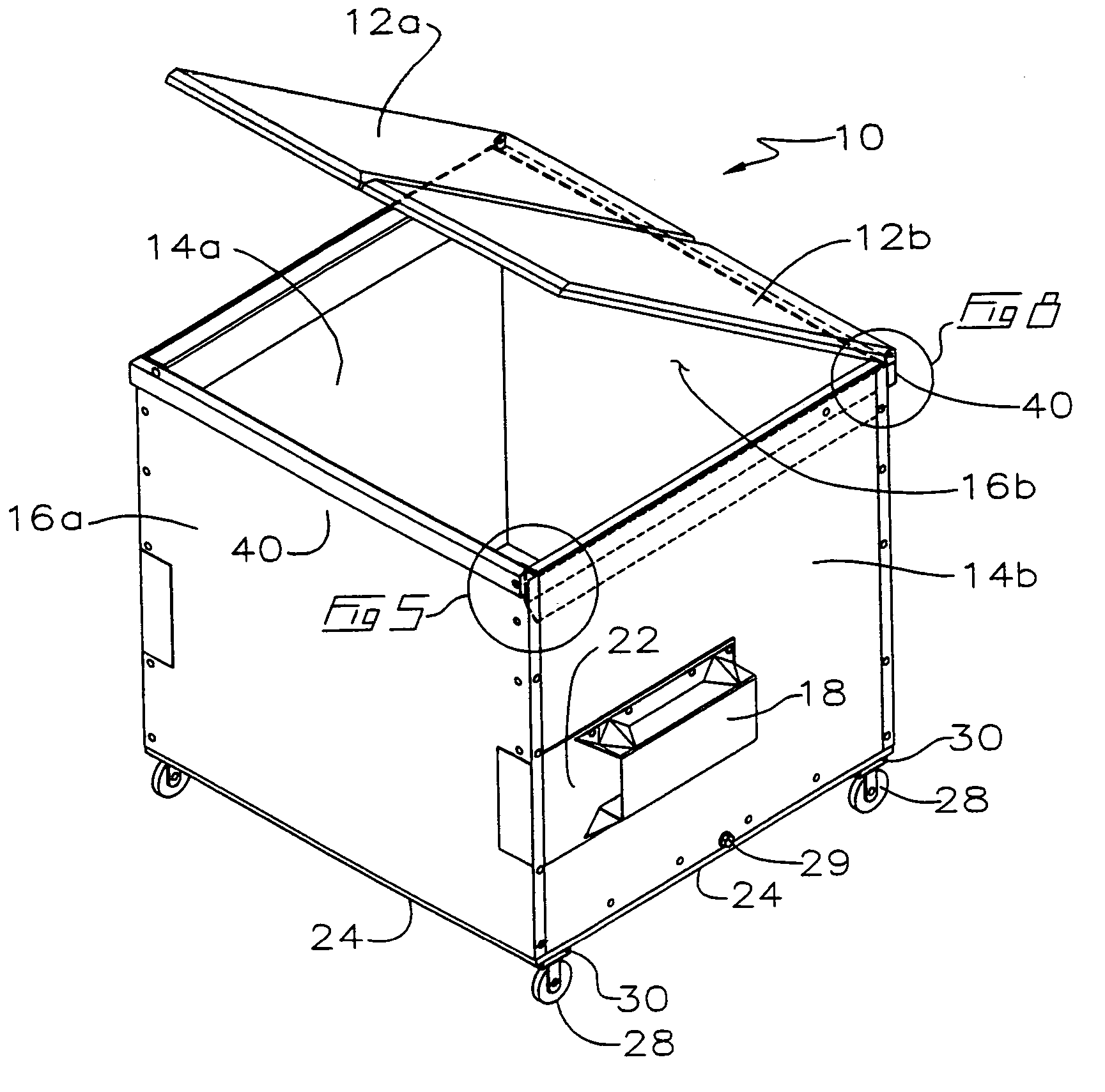
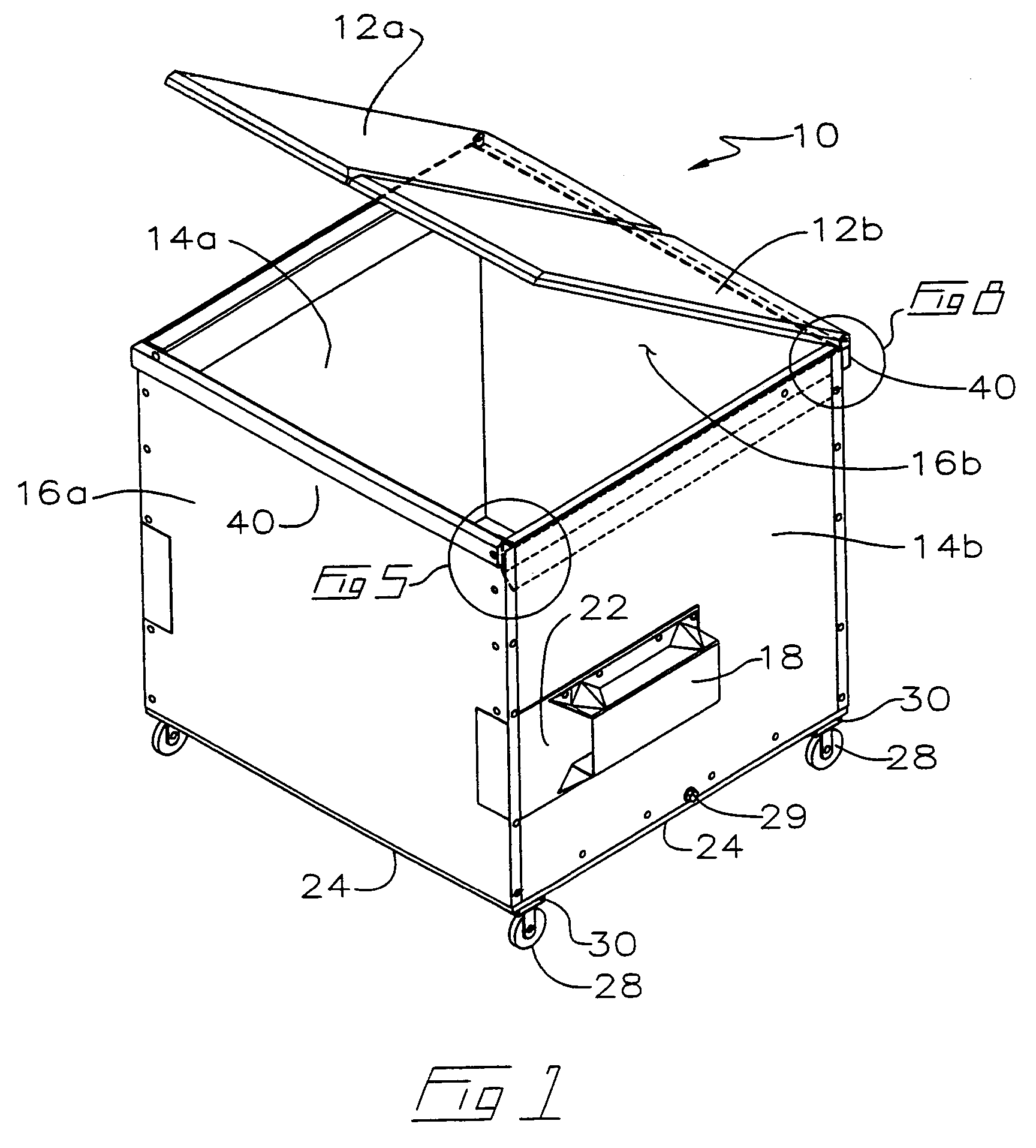
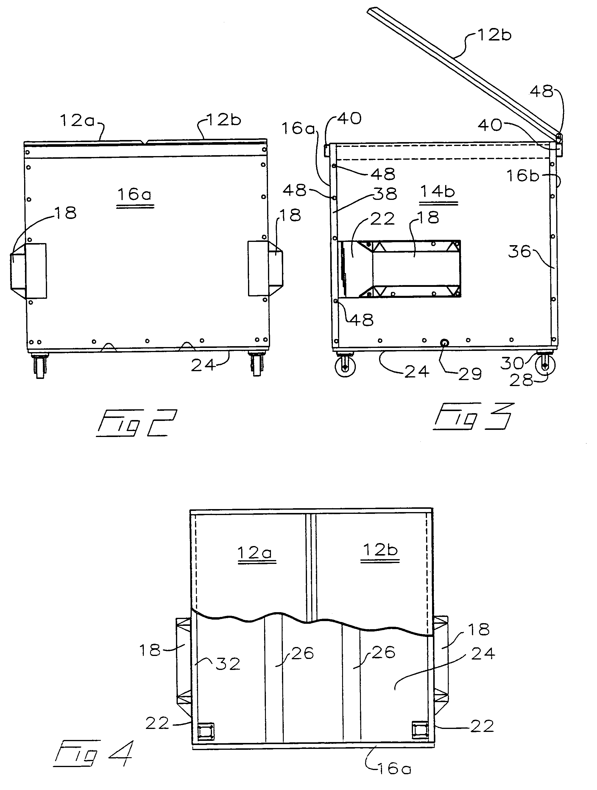
[0032]With reference to the drawings wherein similar characters of reference denote corresponding parts in each view, the modular dumpster according to the present invention is illustrated by way of example in FIG. 1, with corresponding views in FIGS. 2–11. As better explained below, the illustrations are representative of the invention without intending to be limiting as to the type of dumpster to which the invention would apply. Thus in FIG. 1 dumpster 10 is illustrated as having flat hinged lids 12a and 12b, it being understood that other types of dumpsters, for example, so-called cathedral top dumpsters, or dumpsters having inclined covers, whether they be of metal, plastic or other material, and whether they be three yard, four yard, six yard or other sizes are intended to also fall within the scope of the present invention. By way of further example then, side panels 14a and 14b are modularly bolted to front and rear panels 16a and 16b respectively so that, depending on the si...


PUM


Abstract

A rigid modular container includes a floor and an opposite lid, and between the floor and lid opposite rigid rectilinearly-shaped first and second panels, and oppositely disposed rigid rectilinearly-shaped third and fourth panels extending from and between the first and second panels. The panels are removably mounted to the floor. The side edges of adjacent panels are removably mounted to each other as by bolting so that the side edges of the third and fourth panels abut the side edges of the first and second panels. Fastener bracing means such as bolt bracing are mounted to the side edges of the panels and are aligned between adjacent the panels so that fastener receiving apertures therethrough provide for rigid bracing of rigid fasteners such as bolts mounted through and between the fastener bracing means on the adjacent panels. Rigid fasteners such as bolts may thus be mounted through the fastener bracing means on the adjacent the panels.

Description

CROSS REFERENCE TO RELATED APPLICATION[0001]This application claims priority from U.S. Provisional Patent Application No. 60 / 454,323 filed Mar. 14, 2003 and Canadian Patent Application No. 2,432,197 filed Jun. 13, 2003 entitled Modular Refuse Container.FIELD OF THE INVENTION[0002]This invention relates to the field of refuse containers referred to as dumpsters, and in particular to an improved refuse container of modular design.BACKGROUND OF THE INVENTION[0003]Conventional so-called dumpsters, that is, metal refuse containers for storing garbage prior to pick up by a garbage truck, are well known. Such containers are conventionally welded together so as to seal their contents and lend rigidity to the container because the container has to withstand very rough treatment. Damage to dumpsters is very common. For example, in conventional dumpsters the corners often rust out, resulting in the welded dumpsters being discarded entirely, or often dumpsters are marred by graffiti and have to...

Claims


Application Information

Patent Timeline
Patent Type & Authority Patents(United States)
IPC IPC(8): B65D6/00B65D8/14B65D6/26B65D25/00B65D85/00B65F1/02B65F1/12B65F1/14B65F1/16
CPCB65F1/02B65F1/122B65F1/1473B65F1/16B65F1/1615B65F1/1646B65F2210/132B65F2220/101Y10S220/908
Inventor SHOLINDER, RALPH
Owner SHOLINDER RALPH
Why Eureka
Try Eureka