
Imaging apparatus including a movable media sensor

a technology of imaging apparatus and sensor, which is applied in the field of imaging apparatus, can solve the problems of sensor housing scratching of print media, defects in print quality, and sometimes showing scratches, and achieve the effect of affecting the print quality

Active Publication Date: 2007-04-03
LEXMARK INT INC
View PDF52 Cites 13 Cited by
  • Summary
  • Abstract
  • Description
  • Claims
  • Application Information

AI Technical Summary

Benefits of technology

The present invention provides an imaging apparatus with a movable media sensor that can be moved into and out of the media path. This allows for better sensing of the print media and reduces the chance of causing scratches on the print media. The media sensor can be positioned in a way that does not affect print quality, regardless of the printer's media input tray. The invention also allows for the media sensor to be used with printers that have a top or bottom loading media input tray.

Problems solved by technology

One challenge associated with such a configuration is that the media sensor places an uneven drag on a sheet of the print media and can cause the sheet to skew during printing, thereby causing defects in print quality.
Another challenge is that the media sensor housing may scratch the print media, and such a scratch may sometimes show up, for example, as a print defect on certain photo papers.
Printers with a bottom loading input tray have an additional difficulty over top loading input tray printers in regard to media type sensing.
Previously C-path printers have performed media type sensing with a non-contact sensor, which is less reliable than a contact sensor.

Method used


Image

  • Imaging apparatus including a movable media sensor
  • Imaging apparatus including a movable media sensor
  • Imaging apparatus including a movable media sensor

Examples


Embodiment Construction

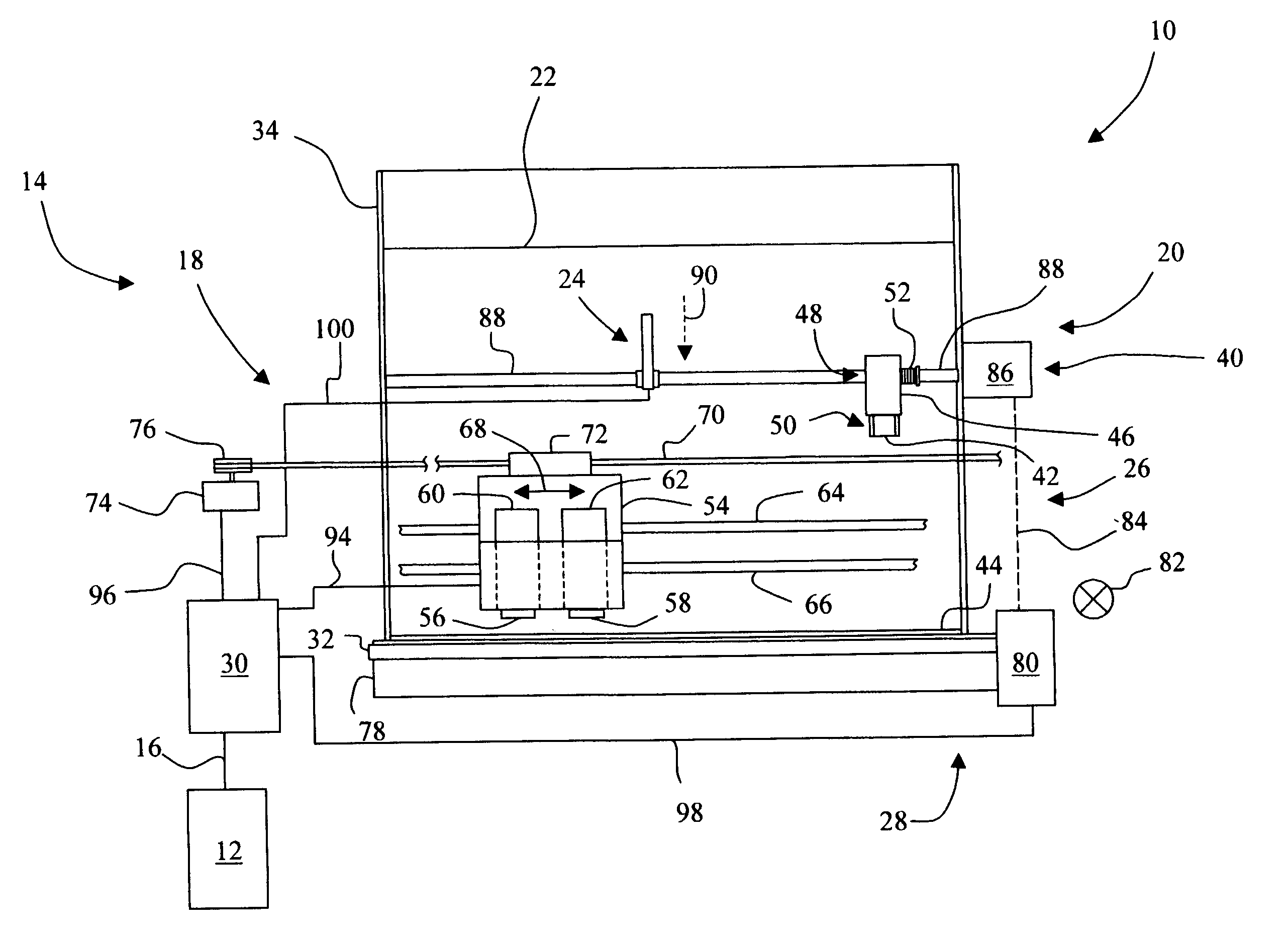
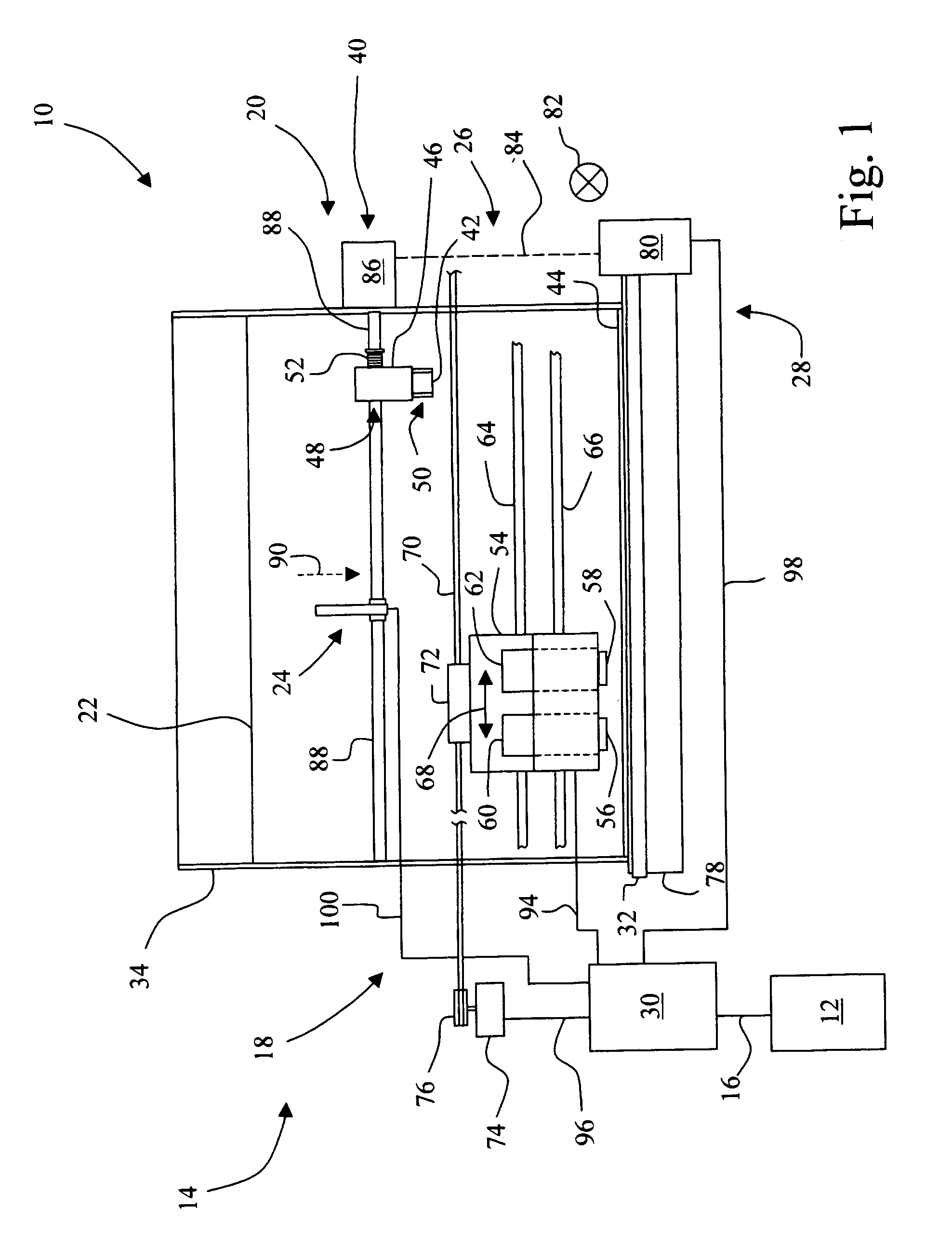
[0021]Referring now to the drawings, and particularly to FIG. 1, there is shown an imaging system 10 embodying the present invention. Imaging system 10 may include a host 12, or alternatively, imaging system 10 may be a standalone system.

[0022]Imaging system 10 includes an imaging apparatus 14, which may be in the form of an ink jet printer, as shown. Thus, for example, imaging apparatus 14 may be a conventional ink jet printer, or may form the print engine for a multi-function apparatus, such as for example, a standalone unit that has faxing and copying capability, in addition to printing.

[0023]Host 12, which may be optional, may be communicatively coupled to imaging apparatus 14 via a communications link 16. Communications link 16 may be, for example, a direct electrical connection, a wireless connection, or a network connection.

[0024]In embodiments including host 12, host 12 may be, for example, a personal computer including a display device, an input device (e.g., keyboard), a p...


PUM


Abstract

An imaging apparatus includes a printing mechanism having a media path. A print media source is provided for supplying a sheet of print media to the printing mechanism. A drive unit is provided, with a drive shaft coupled to the drive unit. A media sensor device is mounted to the drive shaft, wherein as the drive shaft is rotated in a first direction the media sensor device is moved from a first position that is out of the media path to a second position that is in the media path for sensing the sheet of print media. As the drive shaft is rotated in a second direction opposite to the first direction the media sensor device is moved from the second position that is in the media path for sensing the sheet of print media to the first position that is out of the media path.

Description

BACKGROUND OF THE INVENTION[0001]1. Field of the Invention[0002]The present invention relates to an imaging apparatus, and, more particularly, to an imaging apparatus including a movable media sensor.[0003]2. Description of the Related Art[0004]Typically, sensing a media type of a print media works best when the media sensor is in contact with the print media. This has been achieved by placing the media sensor in continuous contact with the input stack of print media. One challenge associated with such a configuration is that the media sensor places an uneven drag on a sheet of the print media and can cause the sheet to skew during printing, thereby causing defects in print quality. Another challenge is that the media sensor housing may scratch the print media, and such a scratch may sometimes show up, for example, as a print defect on certain photo papers.[0005]Printers with a bottom loading input tray have an additional difficulty over top loading input tray printers in regard to ...

Claims


Application Information

Patent Timeline
Patent Type & Authority Patents(United States)
IPC IPC(8): B65H7/14
CPCB65H7/02B65H2402/54B65H2403/72B65H2511/51B65H2553/81
Inventor CHELVAYOHAN, MAHESANCOOK, BRIAN DALEHOWARD, TIMOTHY LORNJOHNSON, KEVIN MATTHEWKLEIN, WILLIAM SCOTTLAWRENCE, MICHAEL WILLIAM
Owner LEXMARK INT INC
Learn More