
Firearm cartridge clip

a technology for firingarms and cartridges, applied in the field of firingarm cartridge clips, can solve the problems of increasing the force required to fully load the clip, increasing the force required to load the clip, and affecting the speed with which the clip is loaded, so as to reduce the spring force, reduce the force on the seat, and improve the effect of accuracy

Inactive Publication Date: 2007-04-10
GATES CRAIG D
View PDF35 Cites 45 Cited by
  • Summary
  • Abstract
  • Description
  • Claims
  • Application Information

AI Technical Summary

Benefits of technology

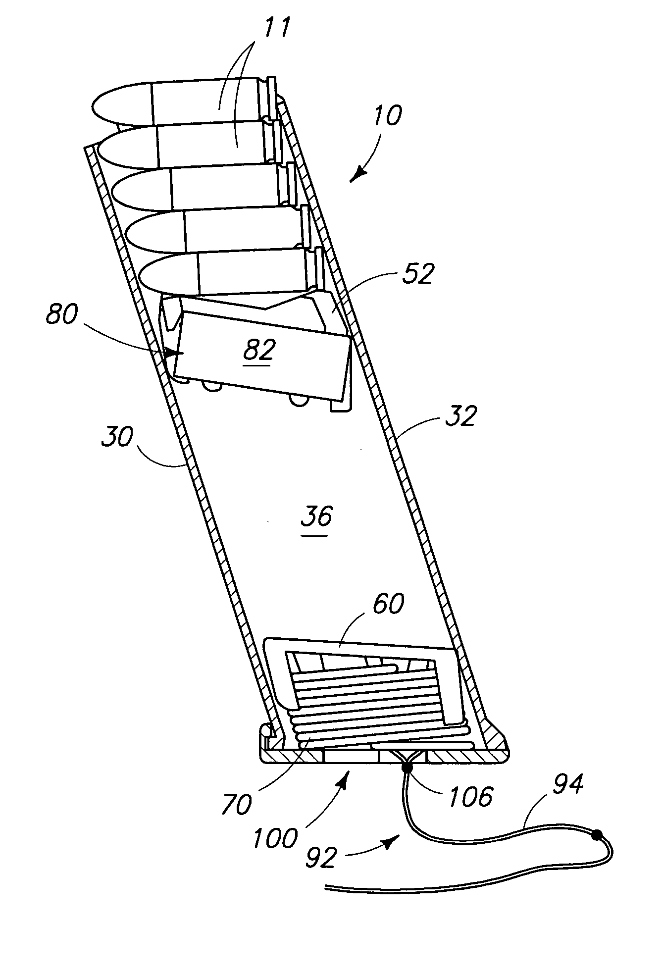
[0006]A firearm clip cartridge is provided with a structure that reduces spring force acting on a cartridge support seat when loading cartridge shells into a housing of the firearm clip cartridge. By reducing force on the seat, cartridge shells can be loaded into the cartridge with greater ease, accuracy, and efficiency.
[0008]According to another aspect, a firearm cartridge clip is provided for receiving and storing a plurality of cartridge shells and for sequentially feeding such loaded cartridge shells to a breech of a firearm when a loaded cartridge clip is attached to the firearm, and includes a cartridge clip housing, a cartridge support seat, an elevator element, a chamber compression spring, and loading facilitating means. The cartridge clip housing has a cartridge shell storage chamber formed therein extending longitudinally along a general housing axis between a bottom end and a top end, said top end having an opening through which the cartridge shells are (1) sequentially manually loaded into the storage chamber for storage, and (2) sequentially fed from the storage chamber into the firearm when the firearm cartridge clip is attached to the firearm. The cartridge support seat is movably mounted in the storage chamber for (1) supporting the cartridge shells stacked one on top of another within the storage chamber substantially transverse to the housing axis, and (2) moving the cartridges along the housing axis. The elevator element, separate from the cartridge support seat, is movably mounted in the storage chamber intermediate the cartridge support seat and the bottom end for movement along the housing axis. The chamber compression spring is mounted in the housing chamber intermediate the elevator element and the bottom end. The chamber compression spring has a known spring rate and an initial compression for normally urging the elevator element and the cartridge support seat toward the top end to sequentially feed cartridge shells to the top end opening. The loading facilitating means is operatively connected to the chamber compression spring for selectively rendering the compression control spring at least partially ineffective to reduce the urging of the cartridge support seat toward the top end and thereby reduce the manual effort required to load the cartridge shells through the top opening and into the housing chamber.
[0009]According to yet another aspect, a firearm cartridge clip is provided for receiving a plurality of cartridge shells and for sequentially feeding such loaded cartridge shells to a breech of a firearm when a loaded cartridge clip is attached to the firearm, and includes a cartridge clip housing, a cartridge support seat, an elevator element, a first chamber compression spring, a second chamber compression spring, and a loading facilitating means. The cartridge clip housing has a cartridge shell storage chamber formed therein extending longitudinally along a general housing axis between a bottom end and a top end, said top end having an opening through which the cartridge shells are (1) sequentially loaded into the storage chamber for storage, and (2) sequentially fed from the storage chamber into the firearm when the firearm cartridge clip is attached to the firearm. The cartridge support seat is movably mounted in the storage chamber for (1) supporting the cartridge shells stacked one on top of another within the storage chamber substantially transverse to the housing axis, and (2) moving the cartridges along the housing axis. The elevator element is movably mounted in the storage chamber intermediate the cartridge support seat and the bottom end for movement along the housing axis. The first chamber compression spring is mounted in the housing chamber intermediate the elevator element and the bottom end. The first chamber compression spring has a known spring rate and an initial compression for normally urging the elevator element and the cartridge support seat toward the top end to feed cartridge shells from the top opening. The second chamber compression spring is mounted in the housing chamber intermediate the cartridge support seat and the elevator element. The second chamber compression spring has a known spring rate and an initial compression for urging the cartridge support seat toward the top end. The loading facilitating means is operatively connected to the elevator element for selectively lowering the elevator means toward the bottom end to reduce the urging of the cartridge support shell toward the top end and thereby selectively reducing the effort required to load the cartridge shells through the top opening and into the housing chamber.
[0010]According to even yet another aspect, a firearm cartridge clip is provided for receiving a plurality of cartridge shells and for sequentially feeding such loaded cartridge shells to a breech of a firearm when a loaded cartridge clip is attached to the firearm, and includes a cartridge clip housing, a cartridge support seat, an elevator element, a chamber compression spring, a movement restraining compression spring, and a loading facilitating means. The cartridge clip housing has a cartridge shell storage chamber formed therein extending longitudinally along a general housing axis between a bottom end and a top end, said top end having an opening through which the cartridge shells are (1) sequentially manually loaded into the storage chamber for storage, and (2) sequentially fed from the storage chamber into the firearm when the firearm cartridge clip is attached to the firearm. The cartridge support seat is movably mounted in the storage chamber for (1) supporting the cartridge shells stacked one on top of another within the storage chamber substantially transverse to the housing axis, and (2) moving the cartridges along the housing axis. The elevator element is movably mounted in the storage chamber intermediate the cartridge support seat and the bottom end for movement along the housing axis. The chamber compression spring is mounted in the housing chamber intermediate the elevator element and the bottom end. The chamber compression spring has an initial compression for normally urging the elevator element and the cartridge support seat toward the top end to feed cartridge shells from the top opening. The movement-restraining compression spring is mounted in the housing chamber intermediate the cartridge support seat and the elevator element. The movement-restraining compression spring has an initial compression for urging the cartridge support seat toward the top end. The loading facilitating means is operatively connected to the elevator element for selectively lowering the elevator means toward the bottom end to reduce the initial compression of the movement restraining compression spring and the urging of the cartridge support seat toward the top end and thereby selectively reducing the manual effort required to load the cartridge shells through the top opening and into the housing chamber.

Problems solved by technology

Many people do not have the prerequisite finger strength or dexterity to manually load a firearm cartridge clip.
Others are only able to partially load the clips, as the dexterity and strength required to fully load the clip exceeds their capabilities.
Furthermore, resistance of the clip spring can slow the speed with which a clip is loaded, as well as tire an individual that has to load multiple clips.
Such modified clips or devices, although reducing the loading resistance, increase the likelihood that the cartridge shells will fall into the clip in a vertical or diagonal orientation, requiring that the clip be emptied and reloaded.

Method used


Image

  • Firearm cartridge clip
  • Firearm cartridge clip
  • Firearm cartridge clip

Examples


Embodiment Construction

[0047]This disclosure of the invention is submitted in furtherance of the constitutional purposes of the U.S. Patent Laws “to promote the progress of science and useful arts” (Article 1, Section 8).

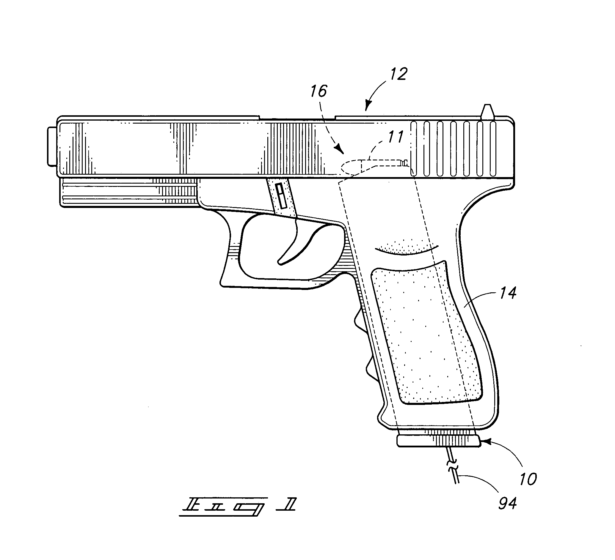
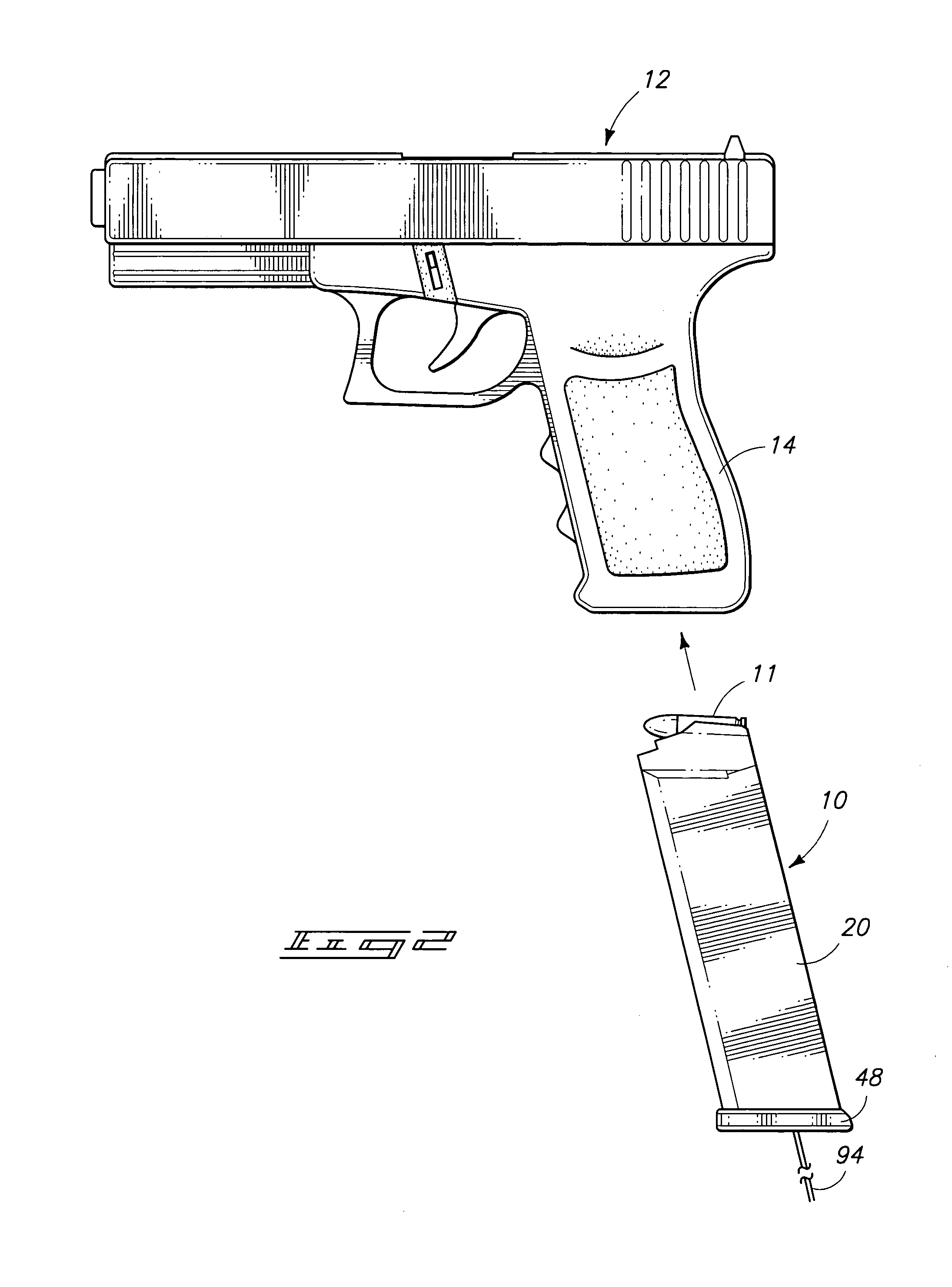
[0048]Referring now to the drawings, there is shown in FIGS. 1 and 2 a preferred embodiment firearm cartridge clip 10. The firearm cartridge clip 10 is designed to receive and store a plurality of firearm cartridge shells 11 therein. The firearm cartridge clip 10 is adapted to be mounted or attached to a clip receiving structure, such as a handle 14, of a firearm 12. The clip 10 is intend to sequentially feed the firearm cartridge shells 11 into a breech 16 of the firearm 12. When the clip 10 becomes empty, it is generally ejected from the firearm by a release latch (not shown) and a full clip 10 mounted in its place. The empty clip 10 is then manually loaded with unspent cartridge shells, one at a time, until the clip 10 contains the desired number or maximum number of cartridge shells 1...


PUM


Abstract

A preferred embodiment of a firearm cartridge clip is disclosed, in which the clip has an elongated housing extending from an open top end to an enclosed bottom end defining an elongated cartridge storage chamber. The clip has a cartridge support seat mounted in the chamber above a separate elevator element. A chamber compression spring is mounted in the chamber between a base at the bottom end and the elevator element to urge the elevator element upward. A separate movement-restraining means is associated with the cartridge support seat to resist downward movement of the seat from the opening at the top end. The clip has a loading facilitating means for selectively rendering the compression spring ineffective to urge the seat upward to thereby reduce the manual effort required to load the clip.

Description

TECHNICAL FIELD[0001]This invention relates to firearm cartridge clips having features that facilitate the loading of cartridge shells into the clips.BACKGROUND OF THE INVENTION[0002]Traditional firearm cartridge clips require that the cartridge shells be manually loaded one at a time through an upper opening into the clip overcoming the progressively increasing resistance of a clip spring. Generally, each cartridge shell, as it is being loaded, is pressed against a previously loaded shell requiring considerable finger dexterity and strength. Many people do not have the prerequisite finger strength or dexterity to manually load a firearm cartridge clip. Others are only able to partially load the clips, as the dexterity and strength required to fully load the clip exceeds their capabilities. Furthermore, resistance of the clip spring can slow the speed with which a clip is loaded, as well as tire an individual that has to load multiple clips.[0003]Many attempts have been made to prov...

Claims


Application Information

Patent Timeline
Patent Type & Authority Patents(United States)
IPC IPC(8): F41A9/61F41A9/67F41A9/71
CPCF41A9/67F41A9/71
Inventor GATES, CRAIG D.
Owner GATES CRAIG D
Learn More