Planar light source apparatus and liquid display apparatus

a light source and liquid display technology, applied in fixed installation, lighting and heating apparatus, instruments, etc., can solve the problems of large side light portion, large pattern on the board, and inability to facilitate light-weighted formation and thin-size formation of planar light source apparatus, so as to reduce the area of the board and prevent the expansion of the side light portion

Inactive Publication Date: 2007-04-10
MITSUBISHI ELECTRIC CORP
View PDF5 Cites 36 Cited by
  • Summary
  • Abstract
  • Description
  • Claims
  • Application Information

AI Technical Summary

Benefits of technology

[0011]The invention has been carried out in view of the above-described situation, and it is an object thereof to provide a planar light source apparatus and a liquid crystal display apparatus capable of realizing light-weighted formation and thin-size formation of the apparatus without deteriorating performance of radiating heat radiated from a point light source. Particularly, it is an object of the invention to provide a planar light source apparatus capable of downsizing and thinning the apparatus without enlarging a side light portion even when a number of elements of point light sources is increased.
[0013]According to such a constitution, the portion of the flexible board is flexed to the back side of the end portion of the reflecting plate inclined to the front side and therefore, even when the wiring pattern on the flexible board is complicated and an area of the board is increased, a side light portion can be restrained from being enlarged.
[0014]The planar light source apparatus according to the invention is constituted to further comprise a heat conducting plate for conducting heat produced in accordance with light emittance of the point light source to the cabinet, wherein the conducting plate is smaller than the flexible board and provided on a side of the point light source of the flexible board, and wherein the flexible board is arranged at a rear face of the cabinet by interposing the heat conducting plate therebetween in addition to the above-described constitution. According to such a constitution, heat produced in accordance with light emittance of the respective point light sources is conducted to the cabinet via the heat conducing plate to radiate and therefore, a temperature of a peripheral portion of the point light source can be restrained from being elevated. At that occasion, the heat conducting plate is provided on a side of the point light source of the flexible board and the flexible board is arranged on the back side of the cabinet via the heat conducting plate and therefore, the flexible board can effectively be flexed to the back side of the reflecting plate.
[0015]Further, the planar light source apparatus according to the invention is constituted such that an end portion of the flexible board is drawn out from a draw out hole for drawing out the board provided at a rear face of the cabinet to a side of a rear face thereof in addition to the above-described constitution. According to such a constitution, the end portion of the flexible board is drawn out from the draw out hole to the back side of the cabinet and therefore, even when the wiring pattern on the board is complicated and the area of the board is increased, the side light portion can effectively be restrained from being enlarged. At that occasion, current can be supplied to a light source unit from a side of the rear face of the cabinet via an end portion of the flexible board drawn out from the draw out hole.
[0016]Further, the planar light source apparatus according to the invention is constituted by comprising a refracting device for refracting light from the point light source to a side of the reflecting plate to emit to the hollow region in addition to the above-described constitution. According to such a constitution, light from the point light source is refracted to the side of the reflecting plate by the refracting device to emit to the hollow region and therefore, an amount of light reflected by the reflecting plate can be increased and a path of propagating light propagating in the hollow region can be prolonged. Therefore, light emitted from the side light portion can be taken out from the opening portion by being sufficiently reflected and diffused at inside of the hollow region and therefore, it can be restrained that a vicinity of the side light portion of the opening portion becomes excessively bright. Thereby, planar uniform light can be taken out from the opening portion and therefore, light-weighted formation and thin-size formation of the planar light source apparatus can be achieved.
[0018]According to the planar light source apparatus and the liquid crystal display apparatus of the invention, the portion of the flexible board is flexed to the back side of the end portion of the reflecting plate inclined to the front side and therefore, even when the wiring pattern on the flexible board is complicated and an area of the board is increased, the side light portion can be restrained from being enlarged. Therefore, small-sized formation and thin-size formation of the planar light source apparatus can be achieved. Further, heat produced in accordance with light emittance of the respective point light sources is conducted to the cabinet via the heat conducting plate to radiate and therefore, a temperature of a peripheral portion of the point light source can be restrained from being elevated, light from the point light source is refracted to the side of the reflecting plate by the refracting device to emit to the hollow region and therefore, it can be restrained that a vicinity of the side light portion of the opening portion becomes excessively bright. Therefore, planar uniform light can be taken out from the opening portion without using the light guide plate and light-weighted formation and thin-size formation of the planar light source apparatus can be achieved.

Problems solved by technology

However, in such a planar light source apparatus of a prior art, a light guide plate is used and therefore, there poses a problem that light-weighted formation and thin-size formation of the planar light source apparatus are not facilitated.
Therefore, when a number of elements of the point light sources is increased, the wiring pattern on the board is complicated, an area of the board is increased and therefore, there also poses a problem that a side light portion is large-sized.
As described above, according to the planar light source apparatus of the prior art, the light guide plate is used and therefore, there poses a problem that light-weighted formation and thin-size formation of the apparatus are not facilitated.
Further, when the number of elements of the point light sources is increased, the wiring pattern on the board is complicated, the area of the board is increased and therefore, there poses a problem that the side light portion is large-sized.

Method used


Image

  • Planar light source apparatus and liquid display apparatus
  • Planar light source apparatus and liquid display apparatus
  • Planar light source apparatus and liquid display apparatus

Examples


embodiment 1

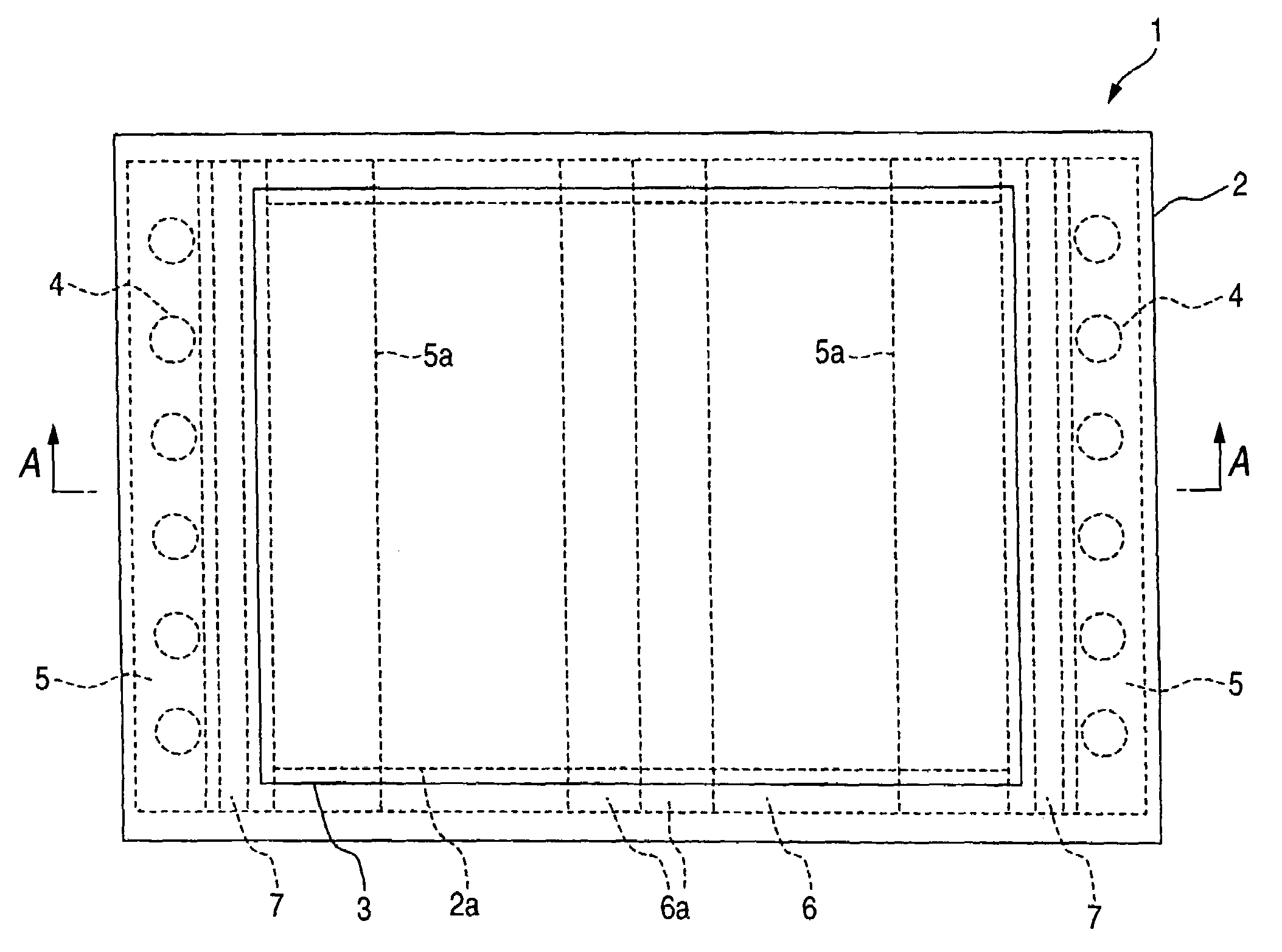
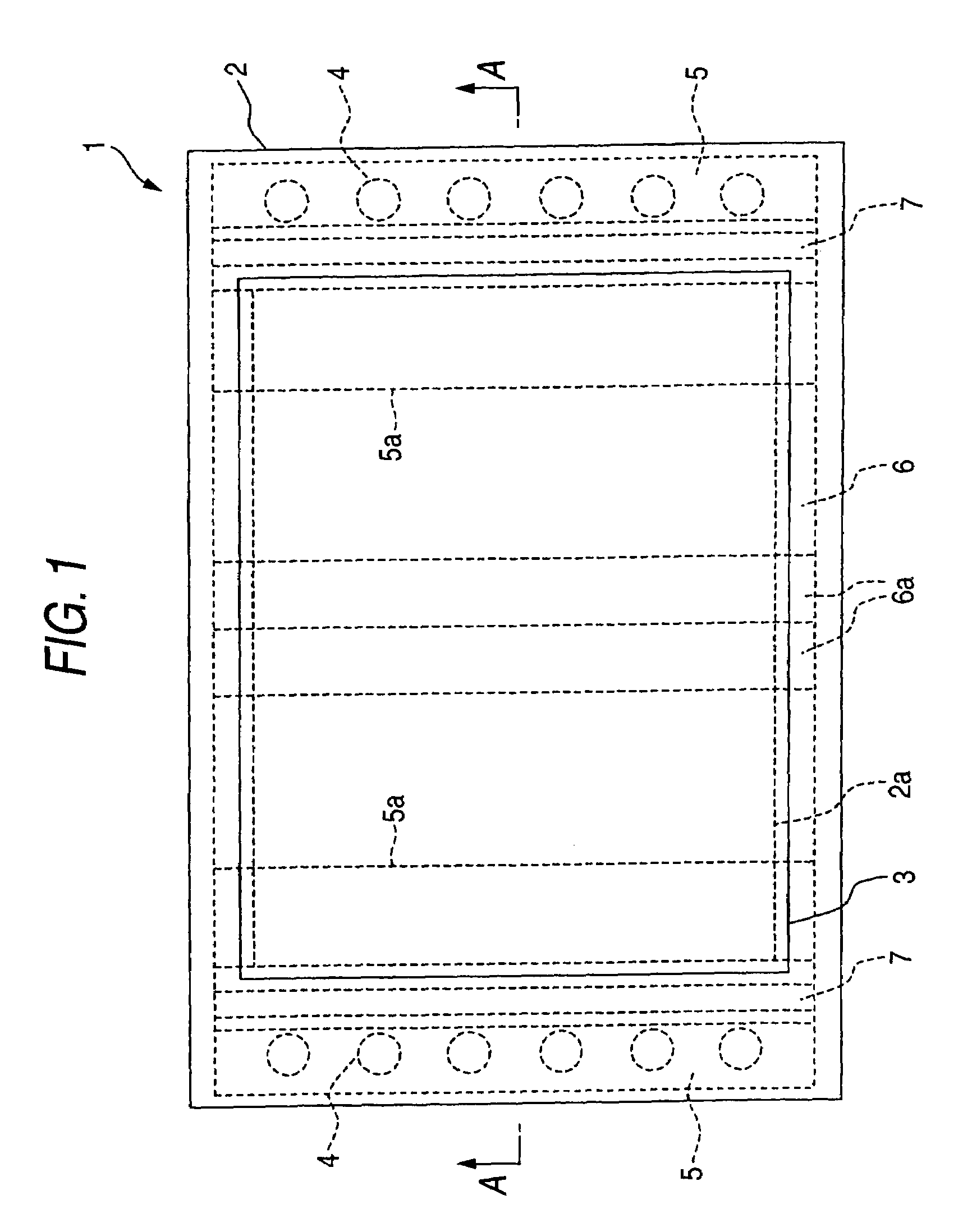
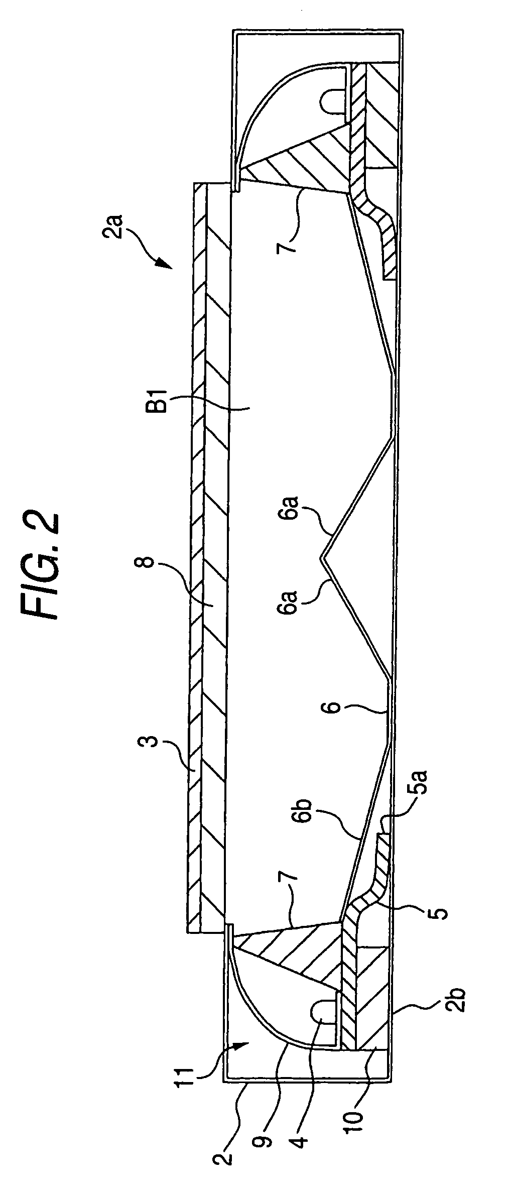
[0033]FIG. 1 and FIG. 2 are views showing an example of an outline constitution of a planar light source apparatus according to Embodiment 1 of the invention, FIG. 1 shows a plane view and FIG. 2 shows a sectional view cut by a line A—A of FIG. 1. A planar light source apparatus 1 according to the invention is a light source apparatus capable of taking out a planar irradiated light uniformly from an opening portion 2a at a front face of a cabinet 2, and one end 5a of a flexible board 5 provided with a plurality of point light sources 4 is arranged to be flexed to a back side of a reflecting plate 6.

[0034]Although use of the planar light source apparatus 1 is not particularly limited, the apparatus is preferable for illuminating a display screen from a rear face by irradiating light to a rear face of a liquid crystal panel (not illustrated). That is, a liquid crystal display apparatus can be constituted by attaching a liquid crystal panel of a transmission type at a front face of the...

embodiment 2

[0072]According to Embodiment 1, an explanation has been given of an example of the case of arranging the respective point light sources 4 at the rear face 2b of the cabinet. In contrast thereto, according to the embodiment, an explanation will be given of a case of arranging the respective point light sources 4 at a side face of the cabinet 2.

[0073]FIG. 12 and FIG. 13 are views showing a constitution example of a planar light source apparatus according to Embodiment 2 of the invention, FIG. 12 shows a sectional view of the planar light source apparatus 30 and FIG. 13 shows the flexible board 5 attached to the side face of the cabinet 2.

[0074]In the case of the planar light source apparatus 30 according to the embodiment, the flexible board 5 provided with the respective point light sources 4 are attached to the side face of the cabinet 2. That is, the flexible board 5 is attached directly to inside of the cabinet 2 without interposing the heat conducting plate 10. The flexible boar...


PUM

PropertyMeasurementUnit
reflectanceaaaaaaaaaa
thicknessaaaaaaaaaa
flexibleaaaaaaaaaa

Abstract

A planar light source including a diffusing plate provided at an opening portion of a cabinet, a plurality of point light sources provided along a hollow region formed on a rear face side of the diffusing plate, a reflecting plate provided at inside of a cabinet relative to the diffusing plate by interposing the hollow region therebetween and arranging an end portion thereof on a side of the point light source to be inclined to a front side, and a flexible board provided with a wiring pattern for supplying power to the respective point light sources, in which an end portion of the flexible board is constituted to be arranged at inside of the cabinet by being flexed to a back side of the end portion of the reflecting plate.

Description

BACKGROUND OF THE INVENTION[0001]1. Field of the Invention[0002]The present invention relates to a planar source apparatus and a liquid display apparatus, further in details, relates to an improvement in a planar light source apparatus for diffusing light of a point light source provided along a hollow region formed on a rear face side of a diffusing plate at inside of the hollow region and irradiating the diffused light to a rear face of a liquid crystal panel or the like.[0003]2. Description of the Related Art[0004]There are a side light of type and an immediate downward type of planar light source apparatus for irradiating a display screen from a rear face thereof by irradiating light to a rear face of a liquid crystal panel. According to a planar light source apparatus of a side light type (also refers to as edge light type), a light source is arranged at a side face of a cabinet, and according to a planar light source of an immediate downward type, a light source is arranged on...

Claims


Application Information

Patent Timeline
Patent Type & Authority Patents(United States)
IPC IPC(8): F21V33/00A47B23/06F21V19/00A47B97/00F21S2/00F21S8/04F21V8/00F21V29/00F21Y101/02G02B6/00G02F1/1333G02F1/1335G02F1/13357
CPCG02B6/0026G02B6/0055G02B6/0068G02B6/0083G02B6/0085G02F1/133603G02F1/133605G02F1/133615F21V29/004G02B6/0073F21V29/767
Inventor SAKAMOTO, TAKUYASAKAI, SEIJIYONEDA, TOSHIYUKI
Owner MITSUBISHI ELECTRIC CORP
Why Eureka
Try Eureka