Reversible floating punch retainer for punch change retainer tool

a technology of retainer tool and punch, which is applied in the field of punch change retainer, can solve the problems of low economic variation of design from standard dimensional criteria for change retainer, and the cost of change retainer is relatively high

Inactive Publication Date: 2007-04-17
DAYTON PROGRESS
View PDF29 Cites 8 Cited by
  • Summary
  • Abstract
  • Description
  • Claims
  • Application Information

AI Technical Summary

Benefits of technology

[0009]The present invention provides for variations in positioning of punch tooling without substantially altering the components comprising the tooling. In particular, alternative positioning of tooling held by a change retainer is provided in a direction perpendicular to the direction of reciprocating movement of the tooling, facilitating alternative positioning of plural punch tools relative to each other.

Problems solved by technology

Further, the cost of change retainers is relatively high compared to conventional stationary punch retainers such that variations in design from the standardized dimensional criteria for change retainers have generally not been economical.

Method used


Image

  • Reversible floating punch retainer for punch change retainer tool
  • Reversible floating punch retainer for punch change retainer tool
  • Reversible floating punch retainer for punch change retainer tool

Examples


Embodiment Construction

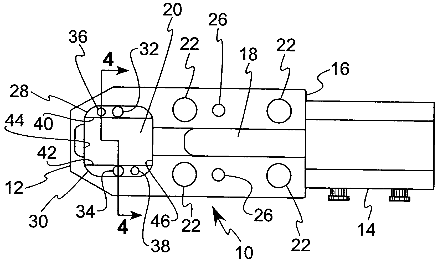
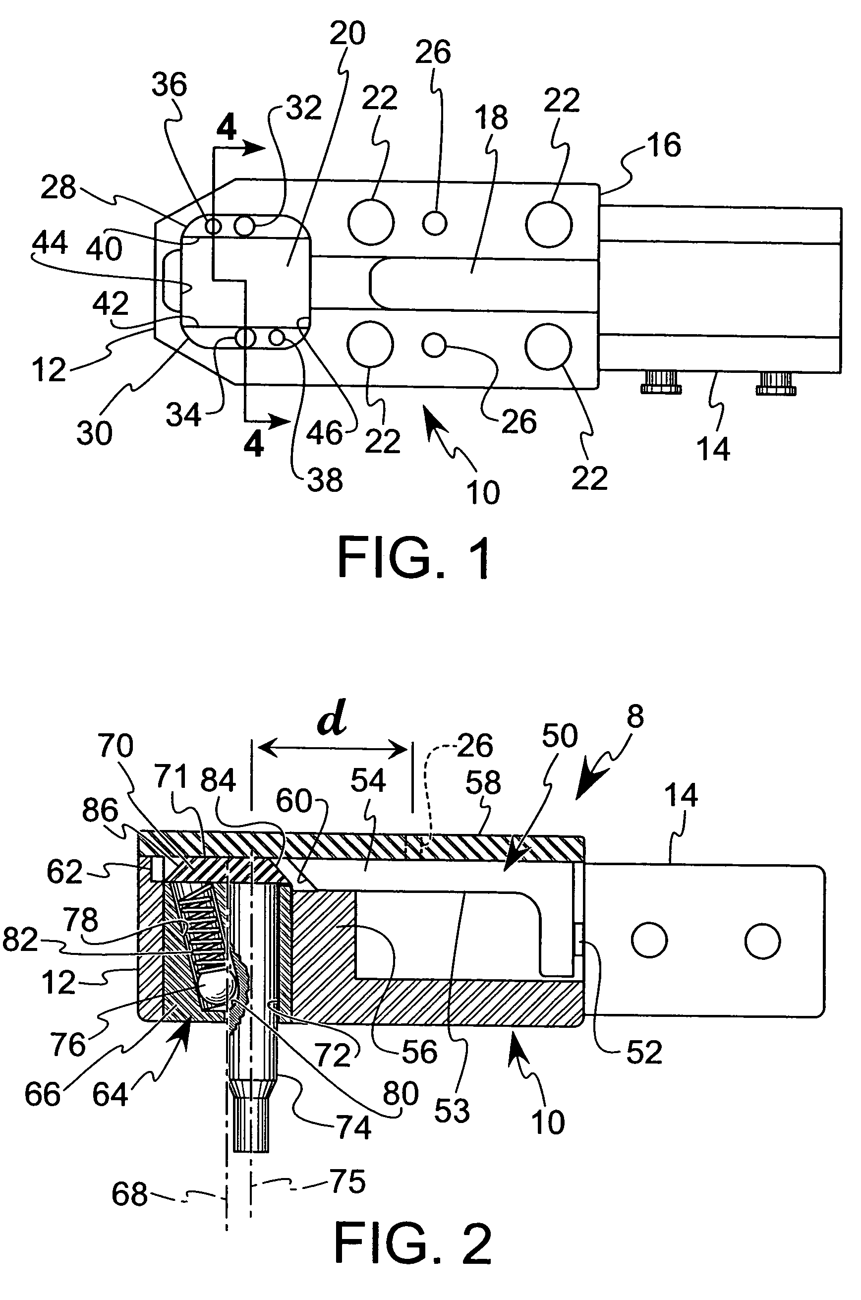
[0022]Referring to FIG. 1 the change retainer of the present invention includes a change retainer body 10 including a nose portion 12 and an actuator 14 at a rear end 16 of the change retainer body 10. The change retainer body 10 includes a gagging member slot 18 located adjacent the actuator 14, and a punch retainer receiving aperture 20 adjacent the nose portion 12 of the change retainer body 10. The change retainer body 10 further includes mounting apertures 22 for receiving fasteners for attaching the change retainer body 10 to the lower surface of a die shoe 24 of a punch press (see FIG. 8). In addition, alignment holes 26 are provided for receiving alignment members, such as dowels, which engage within corresponding holes in the die shoe 24 to precisely position the change retainer body on the die shoe 24.

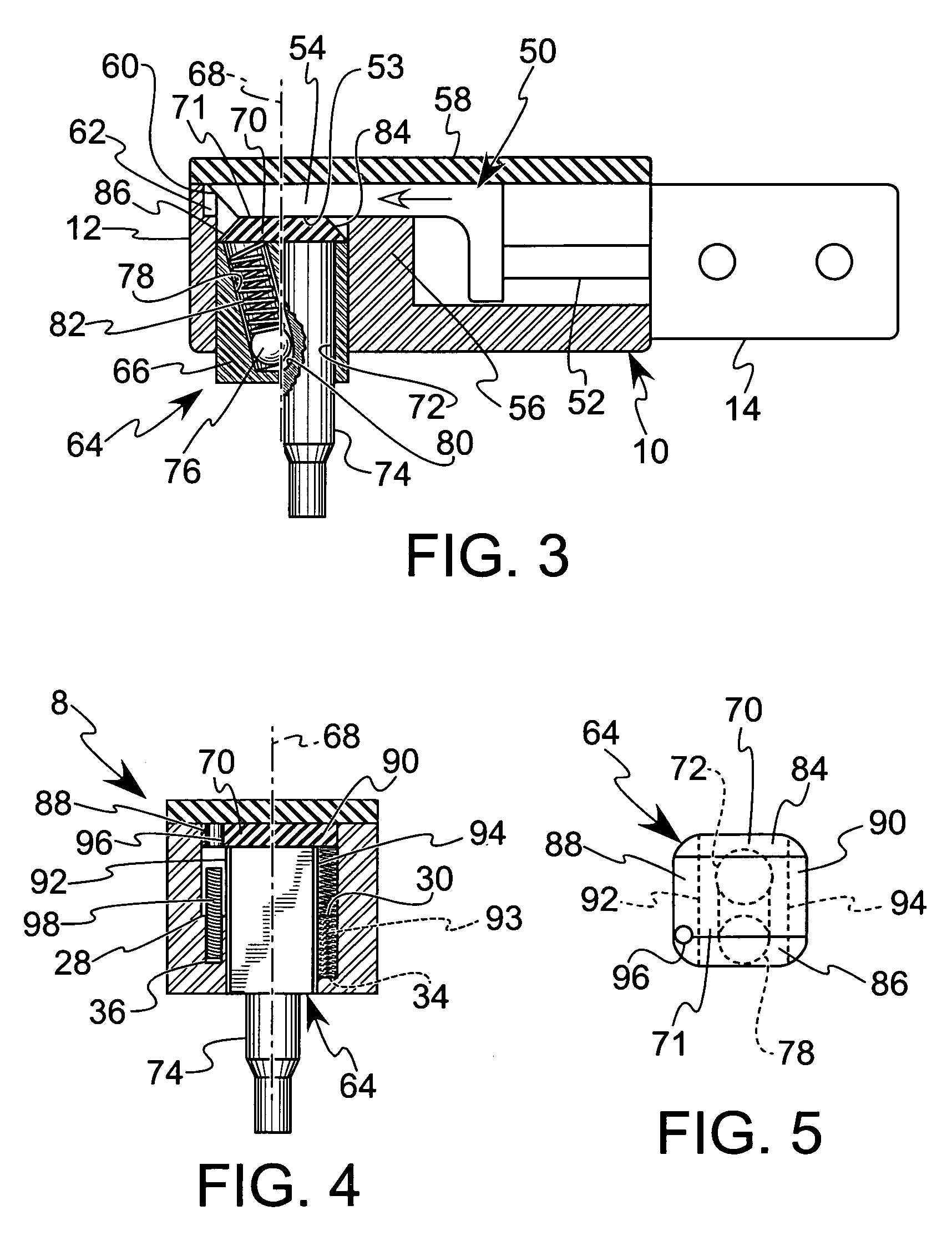
[0023]The retainer receiving aperture 20 includes opposing ledge areas 28, 30 located on either lateral side of the retainer receiving aperture 20. Each of the ledge areas 28...


PUM

PropertyMeasurementUnit
distanceaaaaaaaaaa
volumesaaaaaaaaaa
movementaaaaaaaaaa

Abstract

A punch change retainer for positioning a floating punch in a retracted, disengage position and an extended, engage position. The change retainer includes a change retainer body and a punch retainer receiving aperture extending upwardly through the change retainer body from a bottom surface thereof. A gagging member is located in the change retainer body and is actuable by an actuator between a retracted position distal from a nose portion of the change retainer body and an extended position adjacent the nose portion of the change retainer body. A floating punch retainer is receivable within the punch retainer receiving aperture, and includes an upper end positioned for engagement with the gagging member. A punch receiving hole is defined in the floating punch retainer; where the punch receiving hole is adapted to be rotatably positioned about a longitudinal center line of the floating punch retainer within the punch retainer receiving aperture.

Description

BACKGROUND OF THE INVENTION[0001]1. Field of the Invention[0002]The present invention relates generally to a punch change retainer for use in a punch and die assembly, and more particularly, to punch change retainer including a floating punch retainer which is adapted to reversibly provide different punch retaining locations about a longitudinal center line of the floating punch retainer.[0003]2. Description of Related Art[0004]During manufacture of sheet metal or similar products, it is often necessary to form one or more holes in the workpiece material forming the product. Typically, a punch and die assembly is used to form the holes in such applications, particularly where large production volumes of the products are required. A production punch and die assembly generally includes an upper die shoe supported for movement toward a lower die shoe. A punch retainer is typically mounted to the upper die shoe and secures a punch to the die shoe. The punch is movable towards a die bush...

Claims


Application Information

Patent Timeline
Patent Type & Authority Patents(United States)
IPC IPC(8): B21D28/24B26F1/14
CPCB21D28/34B26D7/2614B26F1/14Y10T83/9476Y10T83/9423Y10T83/8748Y10T83/9471Y10T83/9461B21D28/24B21D28/00
Inventor GOEDEKING, VAN LYNN
Owner DAYTON PROGRESS
Why Eureka
Try Eureka