
Pattern display device and game machine including the same

Inactive Publication Date: 2007-04-17
KONAMI DIGITAL ENTERTAINMENT CO LTD
View PDF31 Cites 214 Cited by
  • Summary
  • Abstract
  • Description
  • Claims
  • Application Information

AI Technical Summary

Benefits of technology

[0009]The present invention has been made in view of the above problems. An object of the present invention is to make it possible to perform several kinds of overlaid displays (overlapping displays). Another object of the present invention is to provide a display device and a game machine adopting the same capable of performing several kinds of overlapping displays.
[0010]According to one aspect of the present invention, a pattern display device has a front side display unit that is disposed in front of a pattern display unit (back side display unit) capable of displaying a plurality of first display patterns. The front side display unit can display a plurality of second patterns overlapping with the first patterns, and is transparent except for the second patterns. Accordingly, the overlapping display becomes variable and flexible. If this pattern display device is applied to a game machine, the overlapping display can attract player's attention, and a high game selection capability can be provided to the player.

Problems solved by technology

The technique disclosed by Japanese Unexamined Patent Publication No. 2-19182 overlays the LCD screen display on top of the regular patterns, however, the overlaid display is composed of only winning lines and is monotonous and luck excitement for a player.

Method used


Image

  • Pattern display device and game machine including the same
  • Pattern display device and game machine including the same
  • Pattern display device and game machine including the same

Examples


first embodiment

[0041

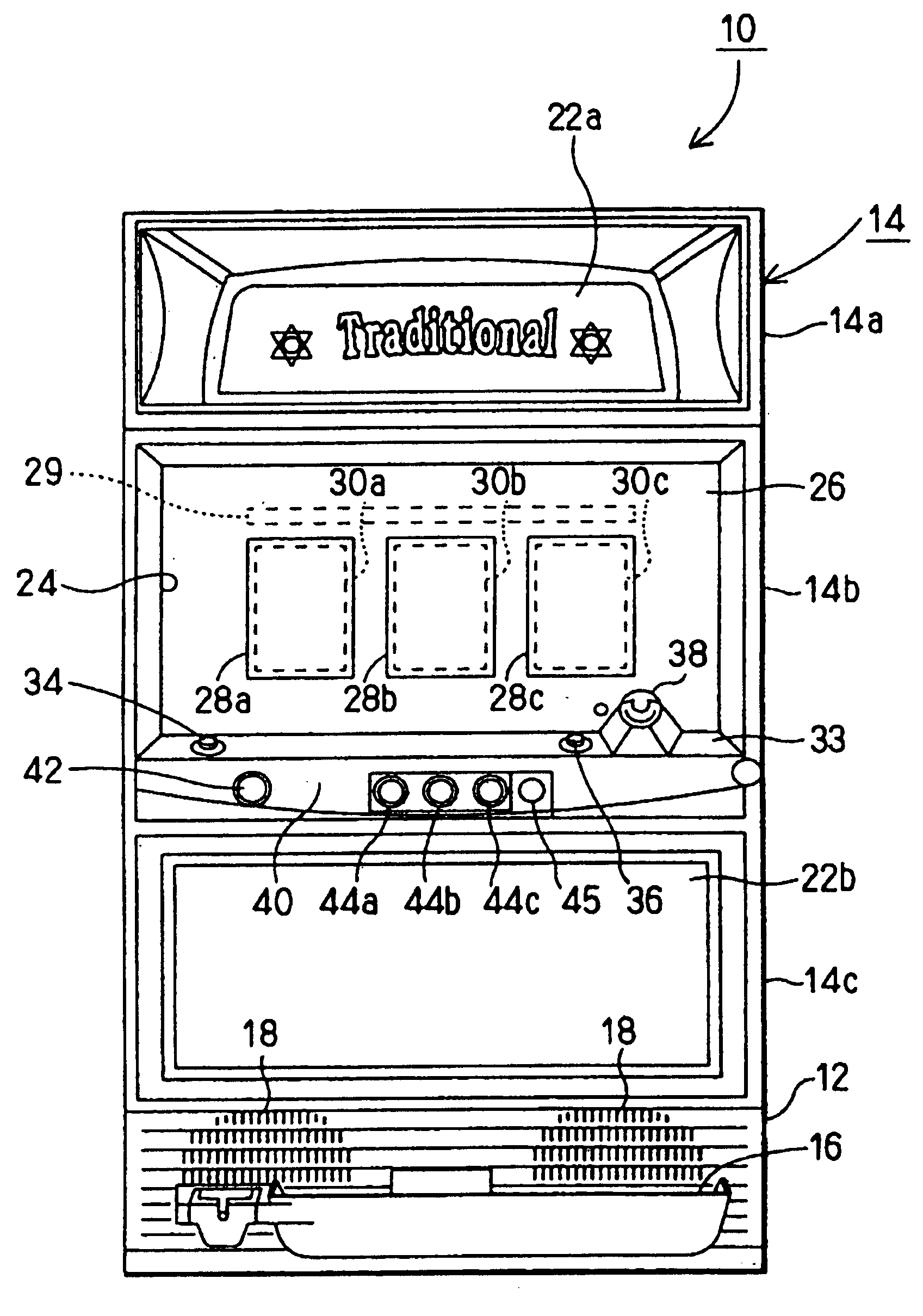
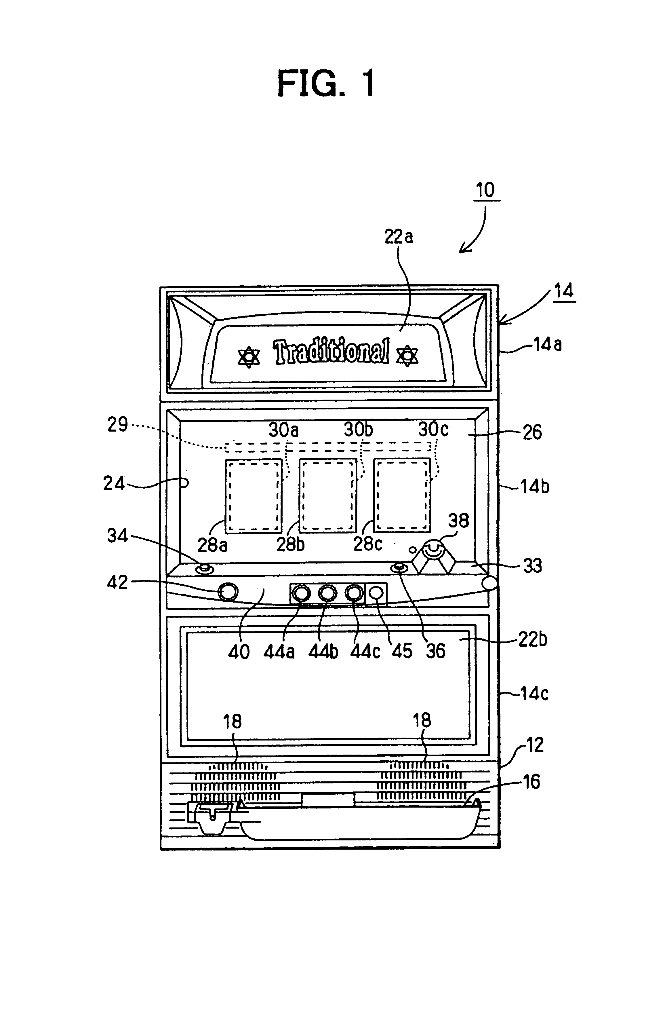
[0042]A first embodiment described here is a case where the invention is materialized as a slot machine. As shown in FIG. 1, a main frame 14 is mounted on the front part of a box 12 of a slot machine 10 via a hinge (not shown), which is normally locked but can be opened like a door when it is unlocked. A receiving dish 16 is provided at the bottom of the main frame 14 and a speaker 18 is provided behind a window having several slits.

[0043]The main frame 14 is divided into a top section 14a, a middle section 14b and a bottom section 14c, wherein the top section 14a and the bottom section 14c are provided with decorative panels 22a and 22b respectively. Although the panel 22a shows the wording “Traditional” in FIG. 1, it is simply a design of the machine and does not mean a prior art. The middle section 14b is provided with displays of patterns and many members that can be operated by a player. Specifically, the middle section 14b has a square opening 24, in which a front panel 2...

second embodiment

[0099

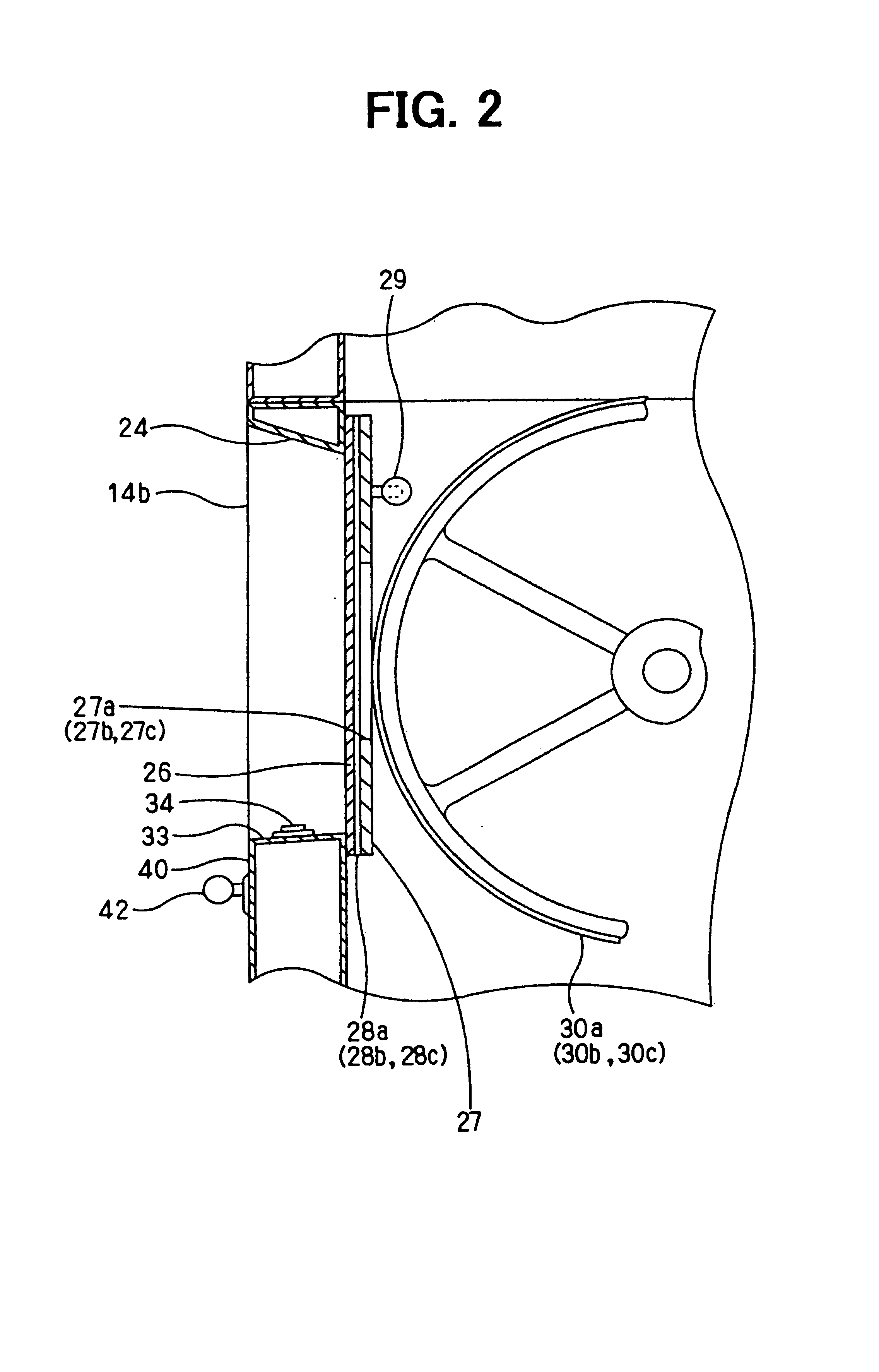
[0100]As described above, in the slot machine 10 of the first embodiment, the display regions of the transparent EL panels 28a, 28b, and 28c are larger than the areas of the reels 30a, 30b and 30c that can be viewed by the player. Therefore, as schematically shown in FIG. 11, the player can view securely the display areas of the reels 30a, 30b and 30c through the transparent EL panels 28a, 28b, and 28c even if the player's viewpoint (posture) slightly changes. The distances between the transparent EL panels 28a, 28b, and 28c and the reels 30a, 30b and 30c are chosen in such a way that the pattern of an adjacent reel (e.g., reel30a) cannot be seen through a certain transparent EL panel (e.g., transparent EL panel 28b). In consequence, the overlapping display does not cause any confusion.

[0101]This advantageous of the invention is studied and explained in more detail as a second embodiment below to improve visibility of the overlapping display and to prevent a blind spot region f...

third embodiment

[0114

[0115]A third embodiment is also to improve visibility of the overlapping display of the back patterns and the overlapping patterns.

[0116]First, a slot machine 15 in the third embodiment is explained with reference to FIGS. 17 to 20. The slot machine 15 has a front frame 11 to which a panel 6 is attached. The panel 6 has a display window 6a at a position facing a player 7 in a state where the machine 15 is installed. A transparent EL panel, 5 is attached to the back surface of the panel 6, which corresponds to a front side display means (display unit). A rotational reel display device 2 is disposed at the back side of the transparent EL panel 5 (inside of a box 100 shown in FIG. 19). The rotational reel display device 2 is composed of three reels 2a, and motors 2b (FIG. 21) for driving the reels 2a. Patterns 2c ($, 7, X, etc.) exemplified in FIG. 18 are drawn on the respective reels 2a, and respective three patterns 2c can be seen through the display window 6a. That is, a 3×3 m...


PUM


Abstract

A game machines has a back side display unit composed of reels for displaying back patterns, and a front side display unit composed of transparent EL panels for displaying overlapping patterns overlapping with the back patterns. The back side display unit and the front side display unit are disposed not to produce blind spot regions of the back patterns. The game machine can provide various overlapping patterns with good visibility and a high game selection capability to a player.

Description

CROSS REFERENCE TO RELATED APPLICATIONS[0001]This application is based upon and claims the benefit of Japanese Patent Applications No. 2000-51314 filed on Feb. 28, 2000, No. 2000-65097 filed on Mar. 9, 2000, and No. 2000-68925 filed on Mar. 13, 2000, the contents of which are incorporated herein by reference.BACKGROUND OF THE INVENTION[0002]1. Field of the Invention[0003]This invention relates to pattern display devices, and game machines including display devices.[0004]2. Description of the Related Art[0005]On one type of game machines, a set of moving patterns is displayed, then the motion of the patterns is stopped, and awarded items (coins and game balls) are dispensed if the resulting (stopped) set of patterns coincides with one of winning sets of patterns. On the other hand, on another type of game machines, a machine is suddenly switched to a different game condition that allows a player to earn many awarded items more easily (a condition called special play or special award)...

Claims


Application Information

Patent Timeline
Patent Type & Authority Patents(United States)
IPC IPC(8): A63F13/00A63F13/08G07F17/32
CPCG07F17/3206G07F17/3288G07F17/3225G07F17/3211
Inventor OZAKI, MASAAKIKANEKO, TAKAHISANISHIOKA, KENUCHIDA, TSUNEOKAWAKAMI, HIROSHIAOKI, YOSHIO
Owner KONAMI DIGITAL ENTERTAINMENT CO LTD
Learn More