Intervertebral implant, insertion tool and method of inserting same

a technology of intervertebral implants and insertion tools, which is applied in the field of intervertebral implants, can solve the problems of extreme delicate area in which to insert an intervertebral implant, and achieve the effect of improving the safety and convenience of us

Inactive Publication Date: 2007-04-17
CENTINEL SPINE LLC
View PDF38 Cites 271 Cited by
  • Summary
  • Abstract
  • Description
  • Claims
  • Application Information

AI Technical Summary

Benefits of technology

[0012]The insertion tool usable in combination with the implant preferably has a pair of arms, each of which engages a recess within a keel, each arm having a projection which is moved toward the base of the recess to engage indentations in the base of the recesses to firmly hold the implant. The ar

Problems solved by technology

For example, the area of the cervical vertebral surfaces facing the adjacent cervical intervertebral spaces may be only about 20 percent of the inter

Method used


Image

  • Intervertebral implant, insertion tool and method of inserting same
  • Intervertebral implant, insertion tool and method of inserting same
  • Intervertebral implant, insertion tool and method of inserting same

Examples


Embodiment Construction

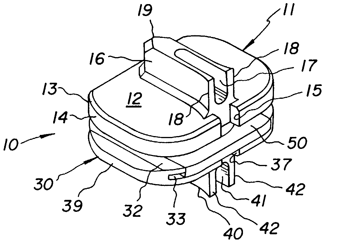
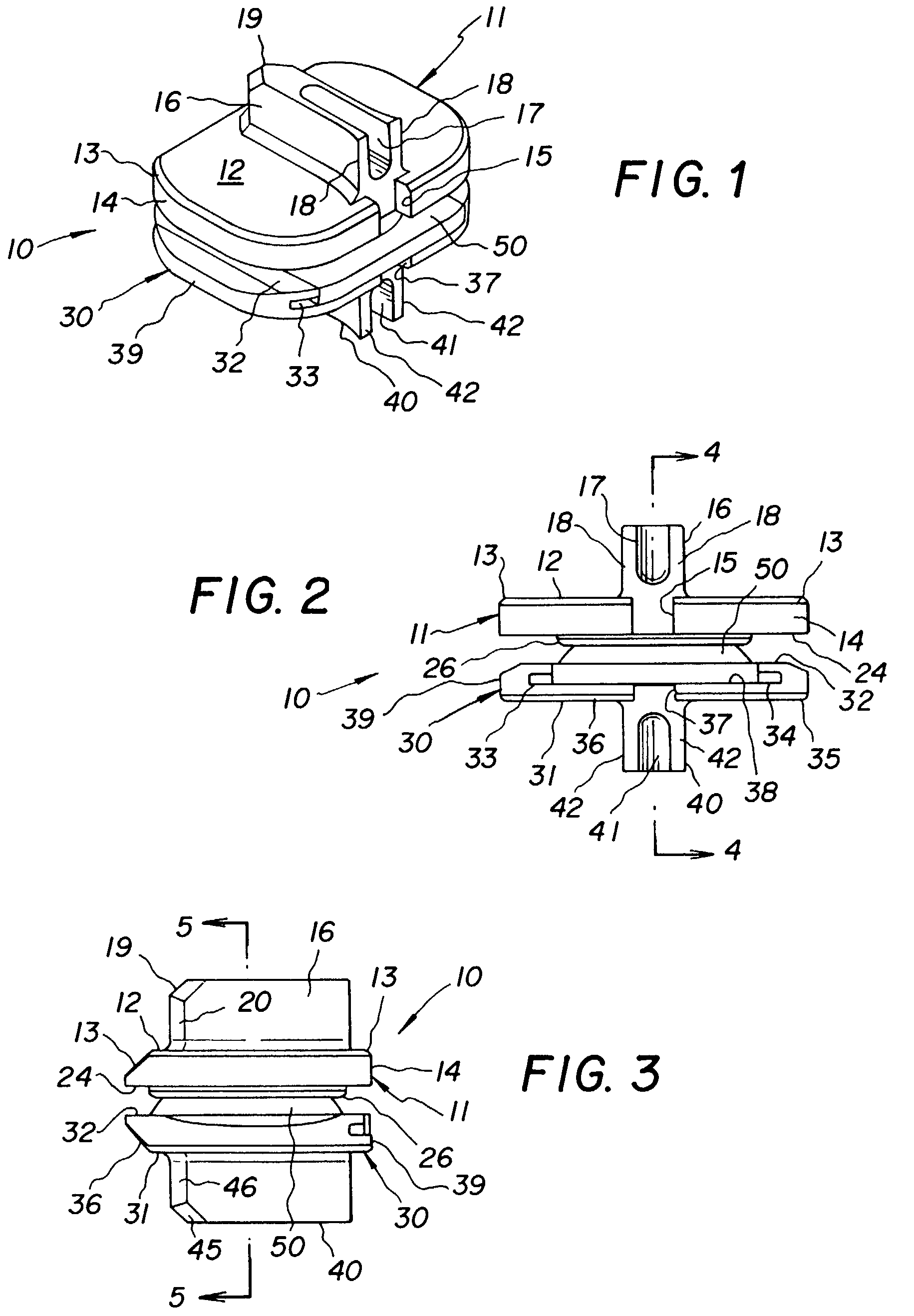
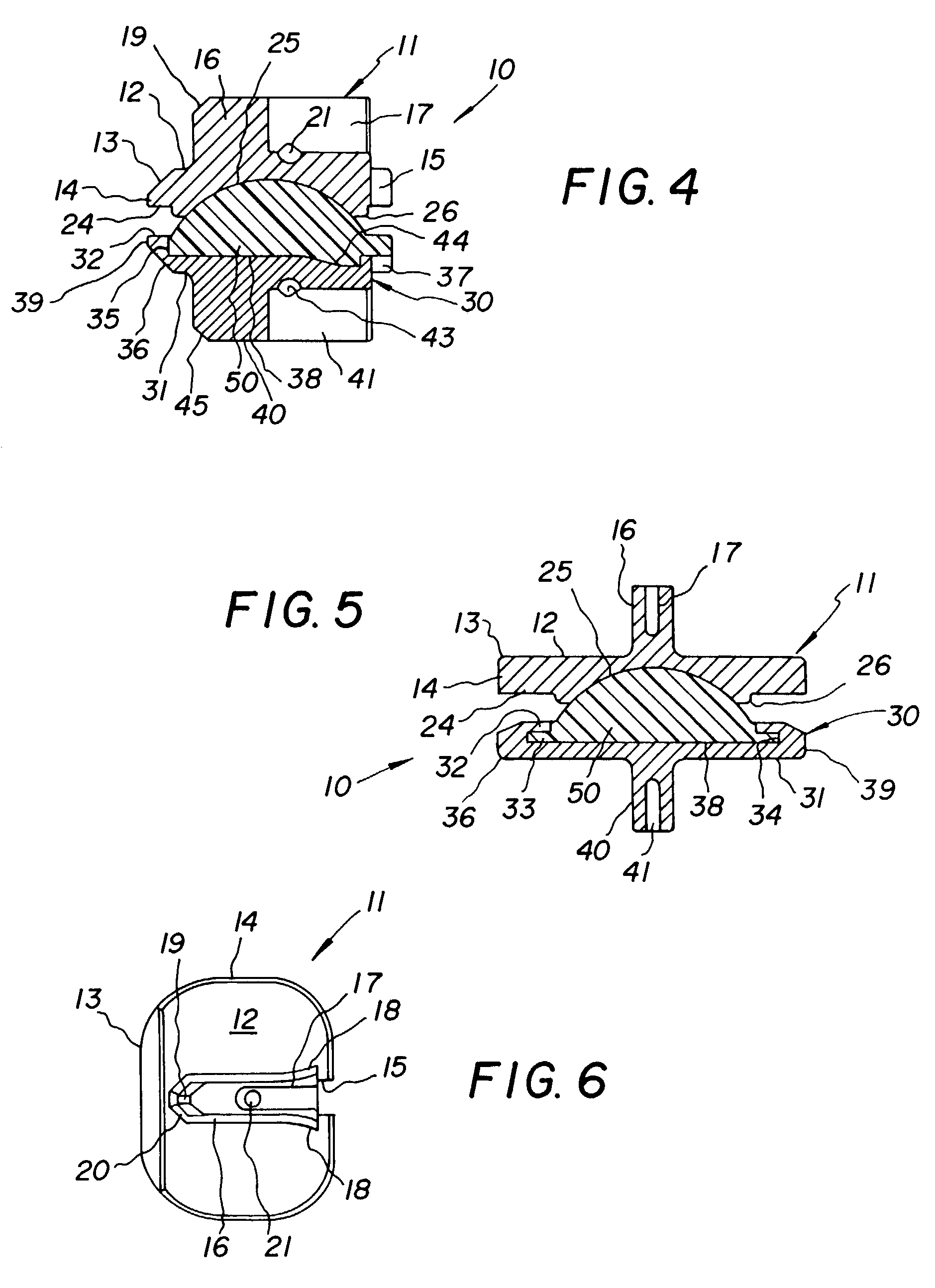
[0039]Referring now to the figures, like elements are represented by like numerals throughout the several views.

[0040]In this application, the words “upper” or “lower” or “uppermost” or “lowermost” or any other words describing the orientation of the intervertebral implant of the present invention are used only for convenience and are not intended to convey any limitation. More specifically, the part of the implant described in this application as the upper part can in fact be positioned as the superior or inferior part within the patient's vertebrae with the other of the two parts being the opposite part. Also, since the intervertebral implant is normally inserted from the front of the patient, the side of the vertebrae toward which the intervertebral implant moves as it is inserted shall be referred to as the anterior side of the vertebrae and the opposite side as the posterior side and the right and left sides as lateral sides. Since the more common manner of insertion is anterio...


PUM

PropertyMeasurementUnit
Heightaaaaaaaaaa
Plasticityaaaaaaaaaa

Abstract

An intervertebral implant, alone and in combination with an insertion tool for inserting same and a method for inserting same. The implant has upper and lower parts which have universal movement relative to each other. Each of the upper and lower parts also has a surface engaging an adjacent vertebrae. Each part has a keel extending from said surface into a cutout in the adjacent vertebrae, and each keel has an anterior opening recess therein. An insert tool has a pair of arms which are received in the recess of the keels through the anterior opening to securely hold and insert the implant. Projections and matching indentations in each arm and the base of its recess securely attached each arm within its keel.

Description

FIELD OF THE INVENTION[0001]This invention relates to intervertebral implants, and in particular, to a new and improved intervertebral implant and to an insertion tool and a method for inserting same.BACKGROUND OF THE INVENTION[0002]Historically, when it was necessary to completely remove a disc from between adjacent vertebrae, the normal remedy was to fuse the adjacent vertebrae together. More recently, there have been important developments in the field of disc replacement, namely disc arthroplasty which involves the insertion of an artificial intervertebral implant into the intervertebral space between adjacent vertebrae and which allows movement of the adjacent vertebrae relative to each other in flexion, extension, lateral bending, axial rotation and translation, as well as absorbing axial compression.[0003]One such development is an artificial intervertebral implant as shown in Published Application No. WO 01 / 01893, published Jan. 11, 2001. The instruments for inserting same a...

Claims


Application Information

Patent Timeline
IPC IPC(8): A61F2/44A61B17/56A61F2/00A61F2/30A61F2/46
CPCA61F2/4425A61F2/4611A61F2310/00407A61F2002/30383A61F2002/305A61F2002/30604A61F2002/30616A61F2002/30662A61F2002/30884A61F2002/443A61F2002/4628A61F2220/0025A61F2310/00023A61F2310/00029A61F2310/00179A61F2310/00017A61F2310/00059A61F2310/00101A61F2/44A61F2/30771A61F2002/30827A61F2002/3092A61F2002/3093
Inventor MARNAY, THEIRRYBERTAGNOLI, RUDMAGEE, FRANKECKHOF, STEPHAN
Owner CENTINEL SPINE LLC
Why Eureka
Try Eureka