Driver adaptive collision warning system

a collision warning and driver technology, applied in the direction of process control, process and machine control, pedestrian/occupant safety arrangement, etc., can solve the problems of false alarms, warning may be too late for conservative drivers, and severe consequences on the performance of collision warning systems

Active Publication Date: 2007-04-17
SAMSUNG ELECTRONICS CO LTD
View PDF12 Cites 158 Cited by
  • Summary
  • Abstract
  • Description
  • Claims
  • Application Information

AI Technical Summary

Problems solved by technology

A mis-interpretation of this characteristic, or simply a mis-adjustment, can have severe consequences on the performance of the collision warning system.
On the other hand, the warning may be too late for a driver who is conservative in driving behavior, who tends to drive slowly and keeps a long distance from the leading car.
An error in one direction causes false alarms which are feared to be the primary cause of the above types of systems being disabled, and then of no benefit at all.
And an error in the other direction may allow the system to alert so late as to be useless, and thereby possibly aiding in the potential accident and creating a liability situation.

Method used


Image

  • Driver adaptive collision warning system
  • Driver adaptive collision warning system
  • Driver adaptive collision warning system

Examples


example 1

Driver Model Creation and Determination of Values of PMs

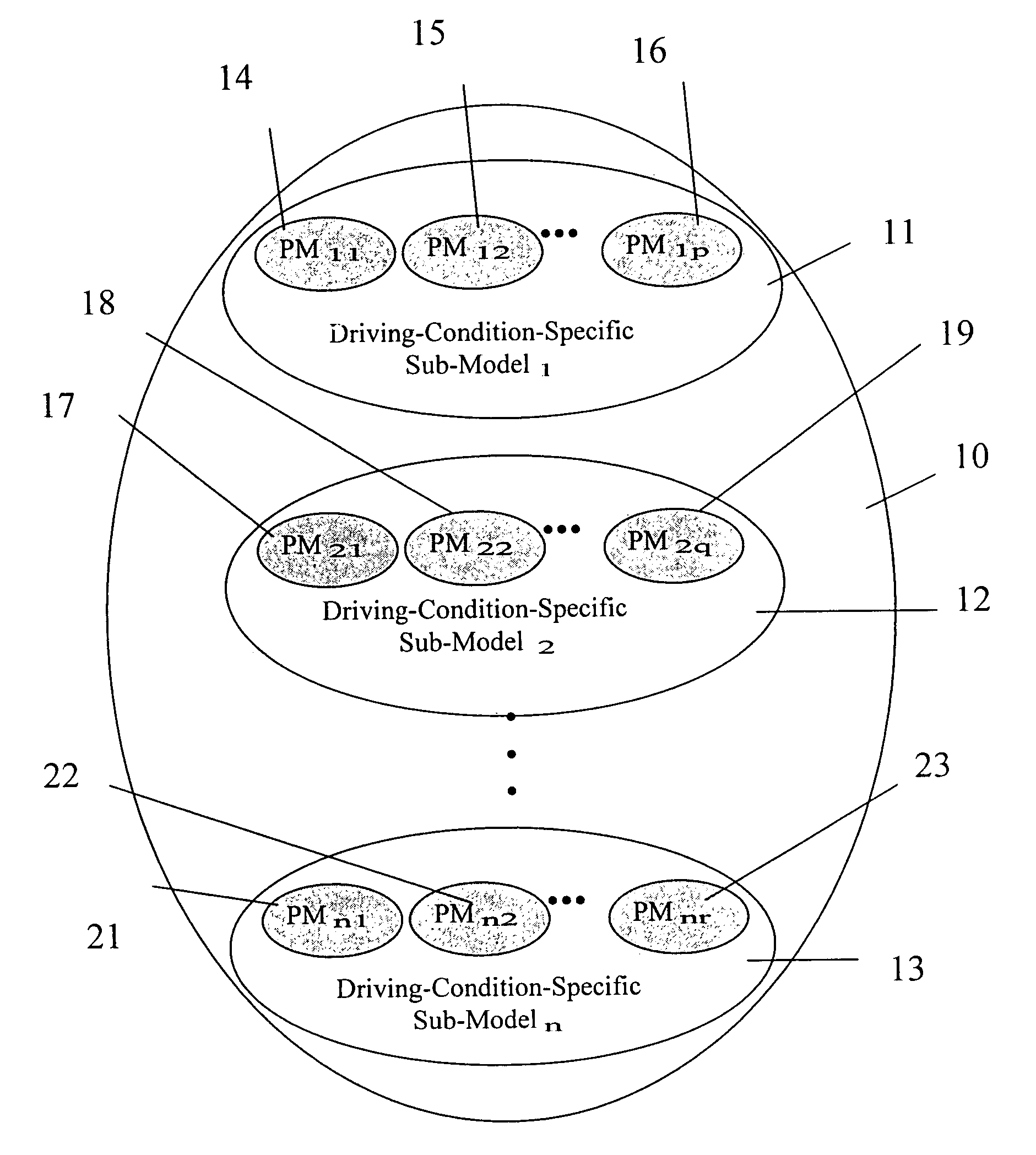
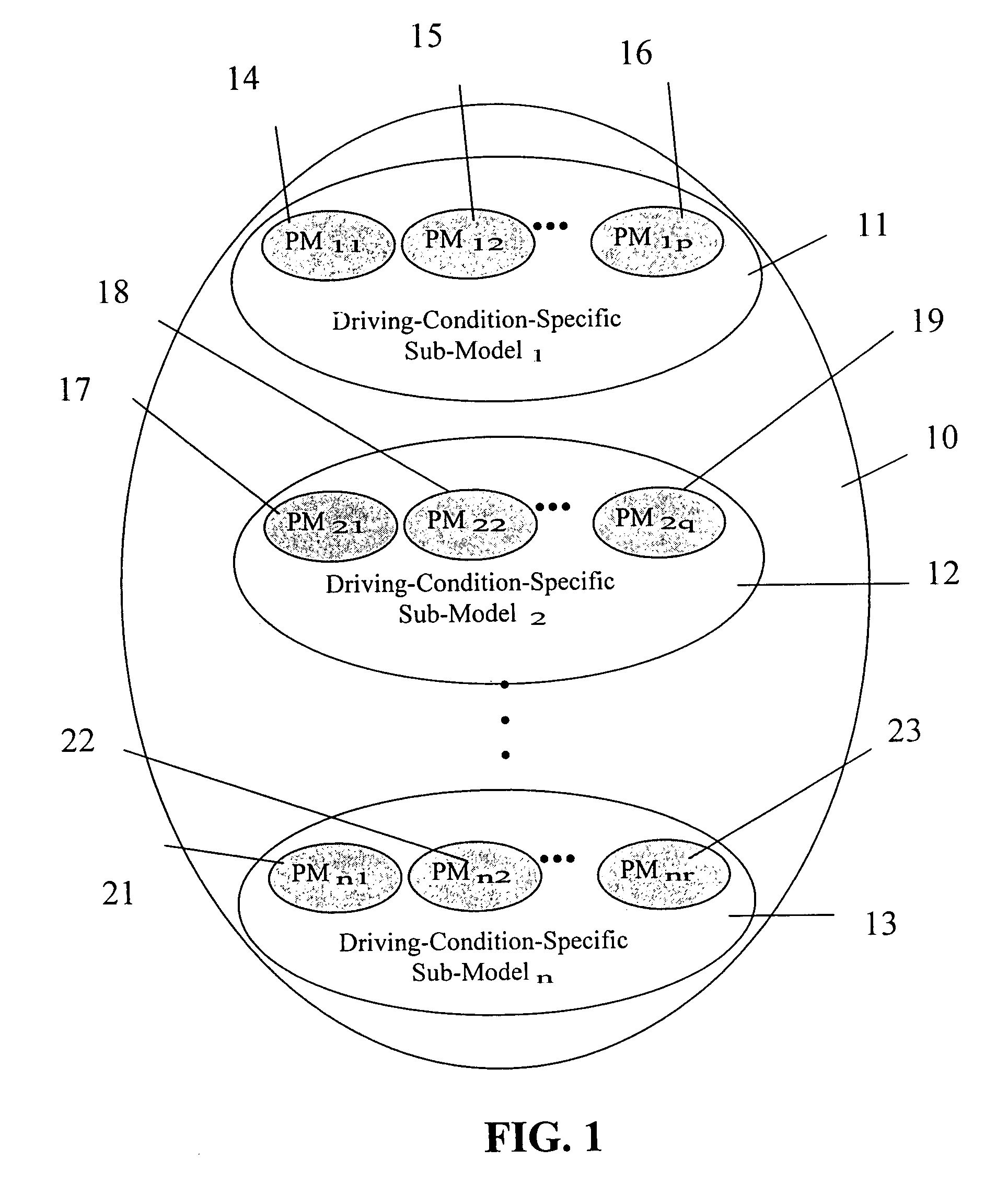
[0062]Experiments were performed using two drivers A and B. Raw driving data related to hostv, host_acc, and Tares PMs, as described hereinabove were collected from the two drivers. Additionally, four artificial driver models C, D, E, F were also created from the data collected from the real driver A. Table. 4 explains how the data in these artificial driver models were simulated. It should be noted that each driver model contained all three PMs.

[0063]

TABLE 4Artificial drivers and how their data were simulatedArtificialDriverHow to simulate dataCReduce hostv by 10% andincrease range by 10% on Driver A's dataDReduce hostv by 15% andincrease range by 20% on Driver A's dataEIncrease hostv by 5% andreduce range by 40% on Driver A's dataFIncrease hostv by 5% andreduce range by 20% on Driver A's data

[0064]Once the raw data were collected, they were processed by applying appropriate pre-determined algorithm corresponding to each PM, a...

example 2

Driver Attitude Determination

[0065]The overall driver attitude level was determined according to the following steps:

[0066]Step (1): Obtaining an average value of each PM.

[0067]The average value of the output data stored in each PM (data stored in the PM were represented by values at the percentiles from 0 to 100, as shown in FIGS. 5A–5E) was calculated. This average value represents the driver's aggression level, based on a single parameter. A method to average the data varied, depending on the parameter. For Tares and acceleration PMs, the lowest and highest five percents of data were thrown out. Only the values of the percentiles between 5 and 95 were averaged. For the host vehicle velocity PM, only the hostv values of the percentiles between 80 and 95 were averaged. The average values for all parameters for all drivers were shown in Table 6 hereinbelow.

[0068]Step (2): Calculating parameter-specific attitude level

[0069]To determine the parameter-specific attitude level, a global ...


PUM


Abstract

The present invention involves methods and systems for issuing a collision warning to a driver at timing based on the driver's attitude level. The methods involve the steps of determining the driver attitude level based on the driver's actions in a plurality of driving conditions, determining timing for issuing warning based on the driver attitude level, and issuing warning based on the determined timing. The systems include a first device for collecting data associated with driver attitude, and a second device connected to the first device for determining a driver attitude level. The second device includes a processor for processing the data by applying pre-determined algorithm to determine the driver attitude level. The systems may further include a third device connected to the second device for determining timing for issuing warning corresponding to the driver attitude level, and issuing a warning according to the determined timing. Alternatively or additionally, the third device may include a software for enabling a determination of the rate of change in terms of acceleration and deceleration, and a control for affecting the rate of change. Further, the third device may include a software for enabling a determination of a safety distance and a distance control.

Description

TECHNICAL BACKGROUND[0001]1. Field of the Invention[0002]The present invention relates to car safety system, particularly collision warning system capable of alerting a driver of a collision potential.[0003]2. Description of the Related Art[0004]Automatic collision warning systems for a vehicle operate based on input data relating to the mental and physical condition of the driver including his behavior during adverse road conditions. The input data can be used by the systems to generate output control affecting timing of audio, visual, and tactile collision warnings.[0005]The state of the art for present collision warning systems may require an input from the operator of the vehicle by way of a dash-mounted control knob. The precise degree of this input is the operator's best judgment as to whether they are an aggressive or conservative driver. A mis-interpretation of this characteristic, or simply a mis-adjustment, can have severe consequences on the performance of the collision w...

Claims


Application Information

Patent Timeline
Patent Type & Authority Patents(United States)
IPC IPC(8): G06F17/10B60K31/00B60Q1/52B60R21/01
CPCB60K31/0008B60W50/16B60T2220/02B60W2540/30B60W2050/0029B60W2050/0025B60W2050/143
Inventor OLNEY, ROSS D.MANOROTKUL, SURADECH
Owner SAMSUNG ELECTRONICS CO LTD
Why Eureka
Try Eureka