
Transition molding and installation methods therefor

a technology of transition molding and installation methods, which is applied in the direction of structural elements, building components, decorative arts, etc., can solve the problems of difficulty in covering the gap that may be formed, and the conventional edge molding is encountered

Inactive Publication Date: 2007-04-24
PERGO
View PDF97 Cites 52 Cited by
  • Summary
  • Abstract
  • Description
  • Claims
  • Application Information

AI Technical Summary

Benefits of technology

"The invention is a joint cover assembly for covering gaps between floor panels, such as laminate or wood panels. The assembly includes a body with a foot and two arms, and securing elements for attaching the assembly to the floor panels. The assembly can be used to cover a variety of gaps and can be easily installed and removed. The assembly is designed to provide a smooth transition between floor panels and can be used with different types of floor coverings. The assembly can also be used to cover gaps between tongue-and-groove type panels. The leveling block helps to make the assembly fit smoothly and can be covered with different materials. The assembly is designed to prevent movement after installation."

Problems solved by technology

A problem is encountered, however, when flooring materials that are dissimilar in shape or texture are used.
For example, when a hard floor is placed adjacent a carpet, problems are encountered with conventional edge moldings placed therebetween.
Such problems include difficulty in covering the gap that may be formed between the floorings having different height, thickness or texture.

Method used


Image

  • Transition molding and installation methods therefor
  • Transition molding and installation methods therefor
  • Transition molding and installation methods therefor

Examples


Embodiment Construction

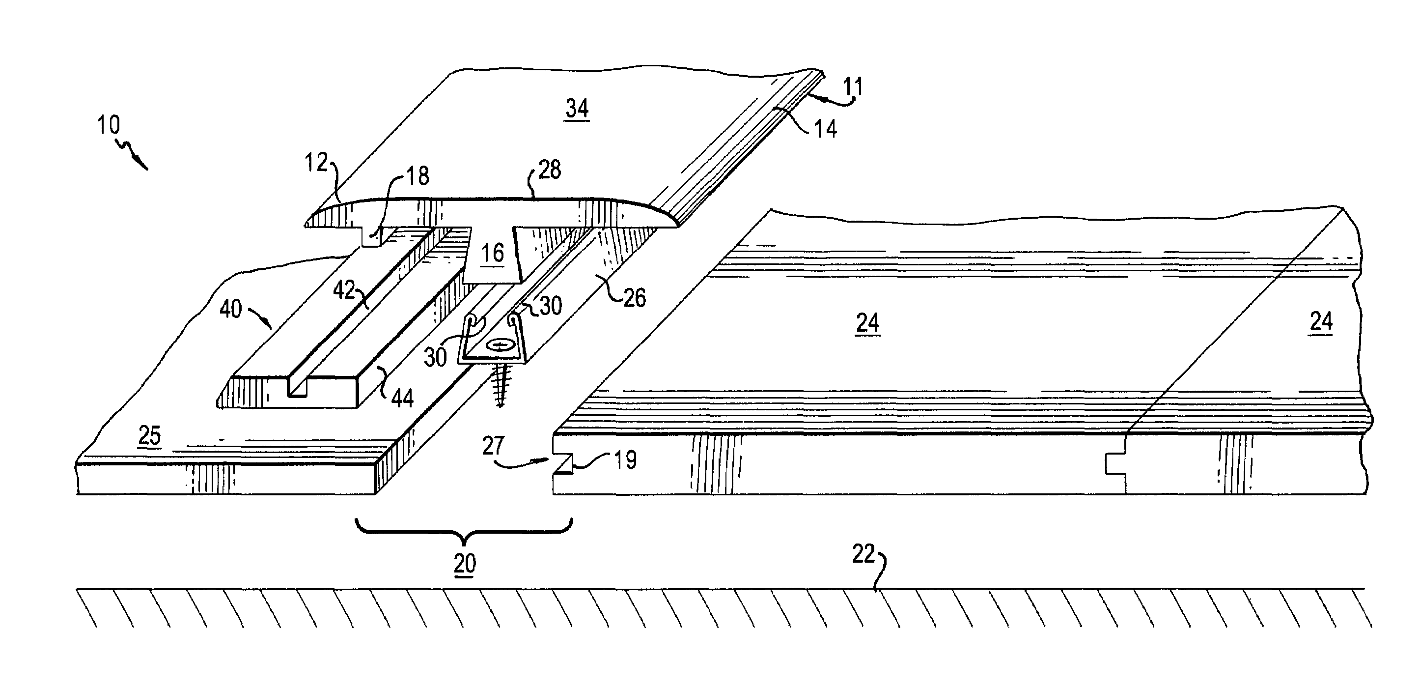
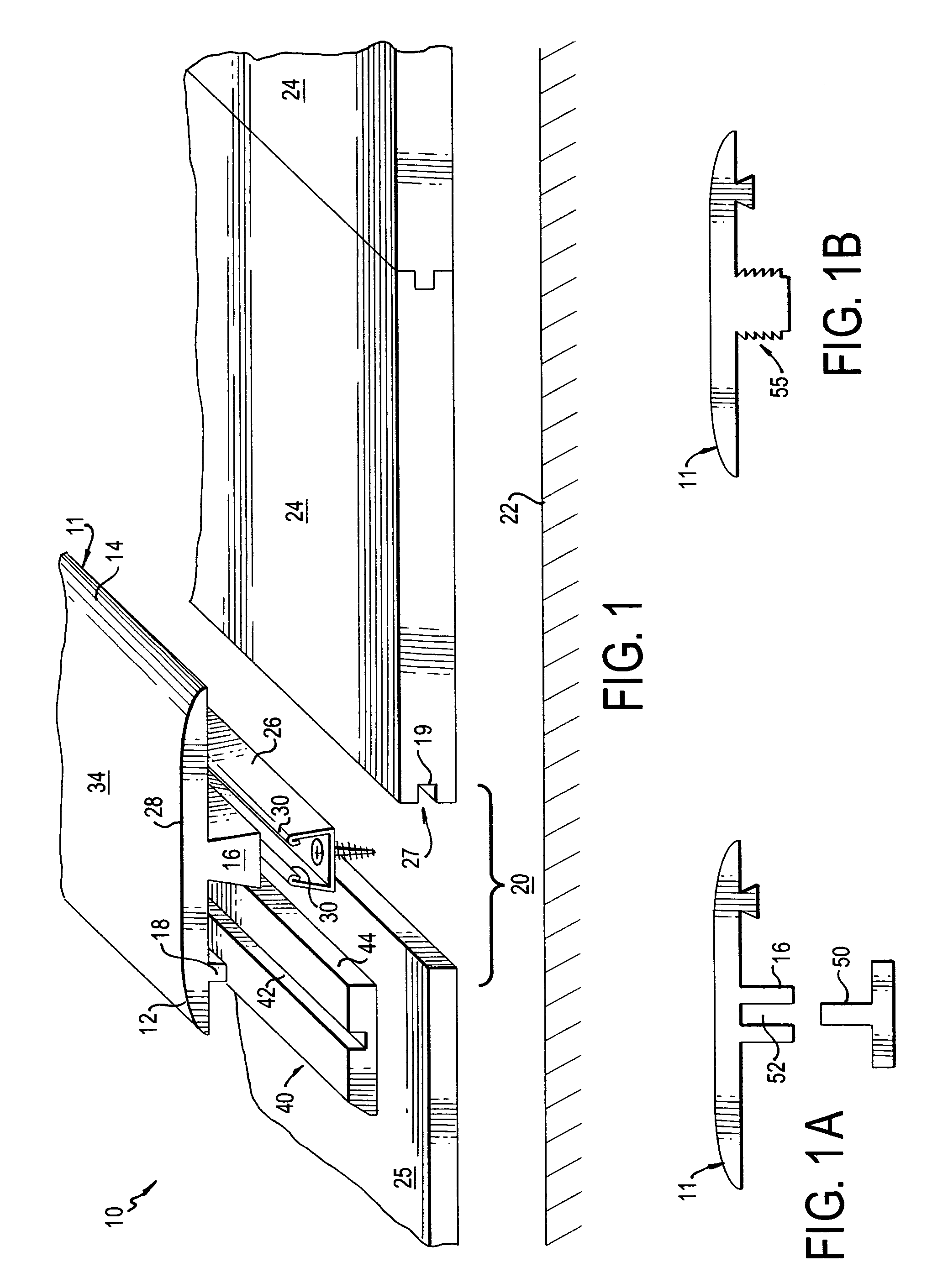
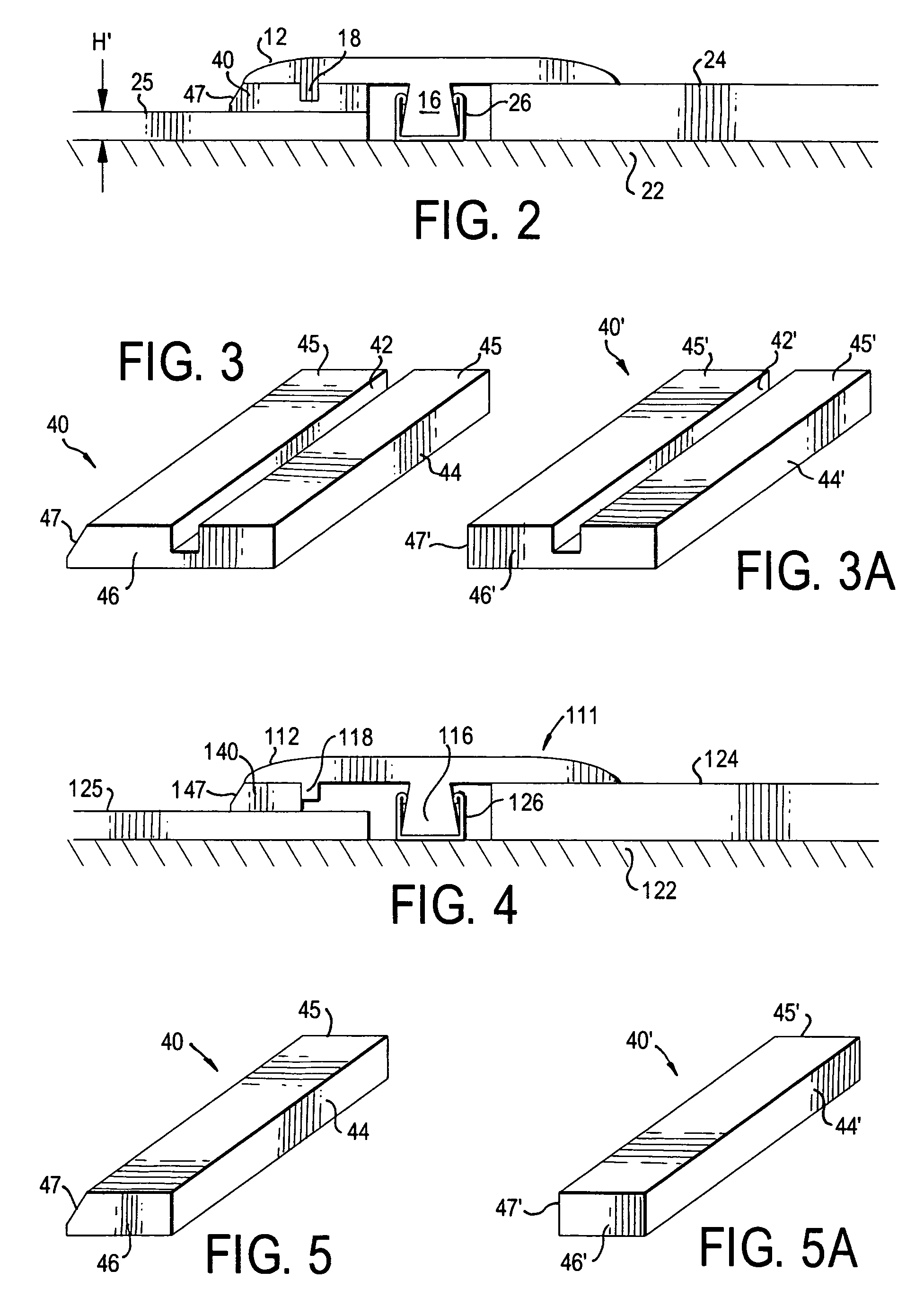
[0036]FIG. 1 shows an exploded view of the various parts of the inventive joint cover assembly 10. The assembly 10 includes a T-shaped molding 11, having a foot 16 formed so that it can fit in a gap 20 between adjacent floor elements 24, 25. FIG. 1 demonstrates a typical use, in which the gap 20 is formed adjacent an edge 27 of a floor element 24. Although FIG. 1 depicts all of the floor elements 24 to be conventional tongue-and-groove type floor panels (having a groove 27 positioned adjacent to the gap 20), this is merely one of any number of embodiments. For example, floor elements 24, 25 need not be the same type of floor element. Specifically, the floor elements 24 can be any type of flooring designed to be used as a floor or placed over a subfloor 22, e.g., tile, linoleum, laminate flooring, concrete slab, parquet, vinyl, turf, composite or hardwood. As is known, laminate floors are not attached to the subfloor 22, but are considered “floating floors.” Although the figures illu...


PUM


Abstract

The invention is a joint cover assembly for covering a gap adjacent an edge of a panel that covers a sub-surface, and a method of covering such a gap. The assembly includes a molding having a foot, a first arm, and a second arm. The foot is positioned along a longitudinal axis of the molding, and the first arm extends generally perpendicularly to the foot. The second arm may also extend generally perpendicularly to the foot. A tab depends from at least one of the first and second arms. At least one of the tab and the foot engage a track in order to position the assembly over the gap. The method includes the steps of placing the foot in the gap, pressing the respective panel engaging surfaces into contact with respective panels, and configuring at least one of the tab and the foot to cooperate to retain the molding in the gap when the assembly is in an installed condition.

Description

[0001]This application is a Continuation-in-Part of U.S. application Ser. No. 11 / 066,099, having been filed May 23, 2005, which application is a Continuation-in-Part of U.S. application Ser. No. 10 / 347,489 (now U.S. Pat. No. 6,860,074), having been filed on Jan. 21, 2003, which in turn is a Continuation-in-Part of U.S. application Ser. No. 09 / 986,414, having been filed on Nov. 8, 2001, now abandoned and U.S. application Ser No. 10 / 748,852, having been filed on Dec. 31, 2003, each of which is herein incorporated by reference in its entirety.BACKGROUND[0002]1. Field of the Invention[0003]The invention is a joint cover assembly that includes a molding, similar to a transition molding between two separate parts, such as a T-Molding, for covering a gap that may be formed between adjacent panels in a generally planar surface, such as between two adjacent flooring or wall or ceiling materials; or between a floor and a hard surface or carpet, or even a riser and a runner in a step (or a ser...

Claims


Application Information

Patent Timeline
Patent Type & Authority Patents(United States)
IPC IPC(8): E04B1/68
CPCE04D1/365E04F19/06E04F11/166E04F19/062E04F19/066E04F19/068E04F19/061E04F11/163E04F19/02E04F19/063
Inventor STANCHFIELD, OLIVER
Owner PERGO
Learn More