Reinforcing support structure for a three-wheeled motor vehicle, and three-wheeled motor vehicle incorporating same

a technology for supporting structures and motor vehicles, applied in the direction of rotary transmissions, bicycles, transportation and packaging, etc., can solve the problems of difficulty in reducing such pivot angles and impairing vehicle mobility, and achieve the effect of suppressing the pivot angle and reducing the tread of rear wheels

Inactive Publication Date: 2007-04-24
HONDA MOTOR CO LTD
View PDF14 Cites 19 Cited by
  • Summary
  • Abstract
  • Description
  • Claims
  • Application Information

AI Technical Summary

Benefits of technology

[0014]Therefore, an object of the present invention is, through improvement of a three-wheeled motor vehicle, to reduce the tread of rear wheels while suppressing the pivot angle of a drive shaft structuring a power transmission mechanism to be a predetermined angle or smaller.

Problems solved by technology

Accordingly, if the total length of the drive shaft is short, it will cause difficulty in reducing such a pivot angle.
Thus, it is hardly applicable to small-sized vehicles, resultantly impairing the vehicle mobility.

Method used


Image

  • Reinforcing support structure for a three-wheeled motor vehicle, and three-wheeled motor vehicle incorporating same
  • Reinforcing support structure for a three-wheeled motor vehicle, and three-wheeled motor vehicle incorporating same
  • Reinforcing support structure for a three-wheeled motor vehicle, and three-wheeled motor vehicle incorporating same

Examples


Embodiment Construction

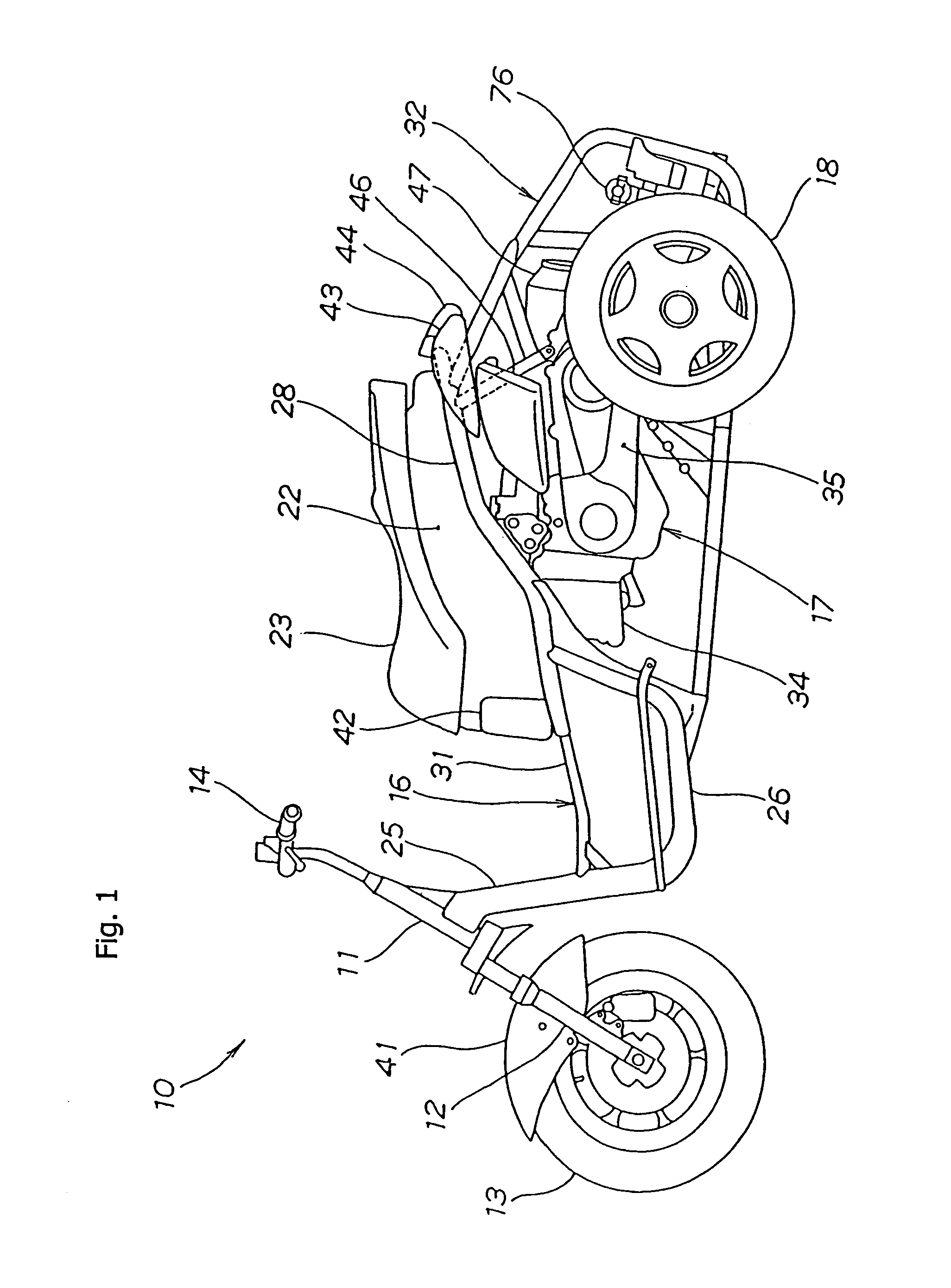
[0057]FIG. 1 is a side view of a three-wheeled motor vehicle according to an illustrative embodiment of the present invention. Therein, a three-wheeled motor vehicle 10 with a rocking mechanism is shown. The three-wheeled motor vehicle 10 is provided with a front fork 12, pivotally attached to a head pipe 11, via a (not-shown) handlebar axis to be steerable. The three-wheeled motor vehicle 10 also includes a front wheel 13 attached to the lower end of the front fork 12, a handlebar 14 attached to the front fork 12 to turn concurrently therewith, and a main frame cage 16 attached to the rear part of the head pipe 11.

[0058]The three-wheeled motor vehicle 10 further includes a powertrain unit 17, attached to the rear part of the main frame cage 16, and rear wheels 18 and 21 (rear wheel 21 locating back behind is not shown in FIG. 1) driven by the powertrain unit 17.

[0059]A housing box 22 is attached to the upper part of the main frame cage 16, and a seat 23 is attached to the upper par...


PUM


Abstract

A three-wheeled motor vehicle includes a through coupling situated between right and left internal shafts and rear wheels, each via a drive shaft. The axial lines of right and left internal shafts are both intersected with a straight line as a rocking axis. If the right and left internal shafts are placed away from each other in the front and rear of the vehicle body, the drive shaft can be placed extensively in the diagonal direction from the right and left internal shafts to the rear wheel side. Using the described structure, the total length of the drive shaft can be increased. In consideration thereof, the bending angle of the drive shaft can be minimized when the rear drive wheels move in the vertical direction, and the track of the rear wheels can be reduced because the drive shaft is placed extensively in the diagonal direction.

Description

CROSS-REFERENCE TO RELATED APPLICATIONS[0001]The present invention claims priority under 35 USC 119 based on Japanese patent application No. 2003-077240, filed Mar. 20, 2003.BACKGROUND OF THE INVENTION[0002]1. Field of the Invention[0003]The present invention relates to a reinforcing support structure for a three-wheeled motor vehicle, and to a three-wheeled vehicle incorporating the described reinforcing support structure. More particularly, the present invention relates to a reinforcing support structures and to a three-wheeled motor vehicle in which a main frame cage is pivotally rockable about a rocking axis, with respect to a rear wheel support structure.[0004]2. Description of the Background Art[0005]One example of a known power transmission for a vehicle has rear wheels attached at the tips of right and left axles that extend concentrically from a differential gear to the right and left sides of the vehicle body, respectively. Examples of this type of design can be found in J...

Claims


Application Information

Patent Timeline
Patent Type & Authority Patents(United States)
IPC IPC(8): B62D61/06B60G9/02B60G3/20B60K17/04B60K17/22B62K5/02B62K5/06B62M17/00
CPCB62K5/027
Inventor KUROKI, MASAHIROTAKAYANAGI, SHINJI
Owner HONDA MOTOR CO LTD
Why Eureka
Try Eureka