
Vehicular power transmission mechanism

Active Publication Date: 2007-10-30
HONDA MOTOR CO LTD
View PDF26 Cites 28 Cited by
  • Summary
  • Abstract
  • Description
  • Claims
  • Application Information

AI Technical Summary

Benefits of technology

[0016]It is an object of the invention is to improve a power transmission mechanism of a vehicle and to reduce the tread of rear wheels, keeping an angle of the bend of a drive shaft at a predetermined angle or less.
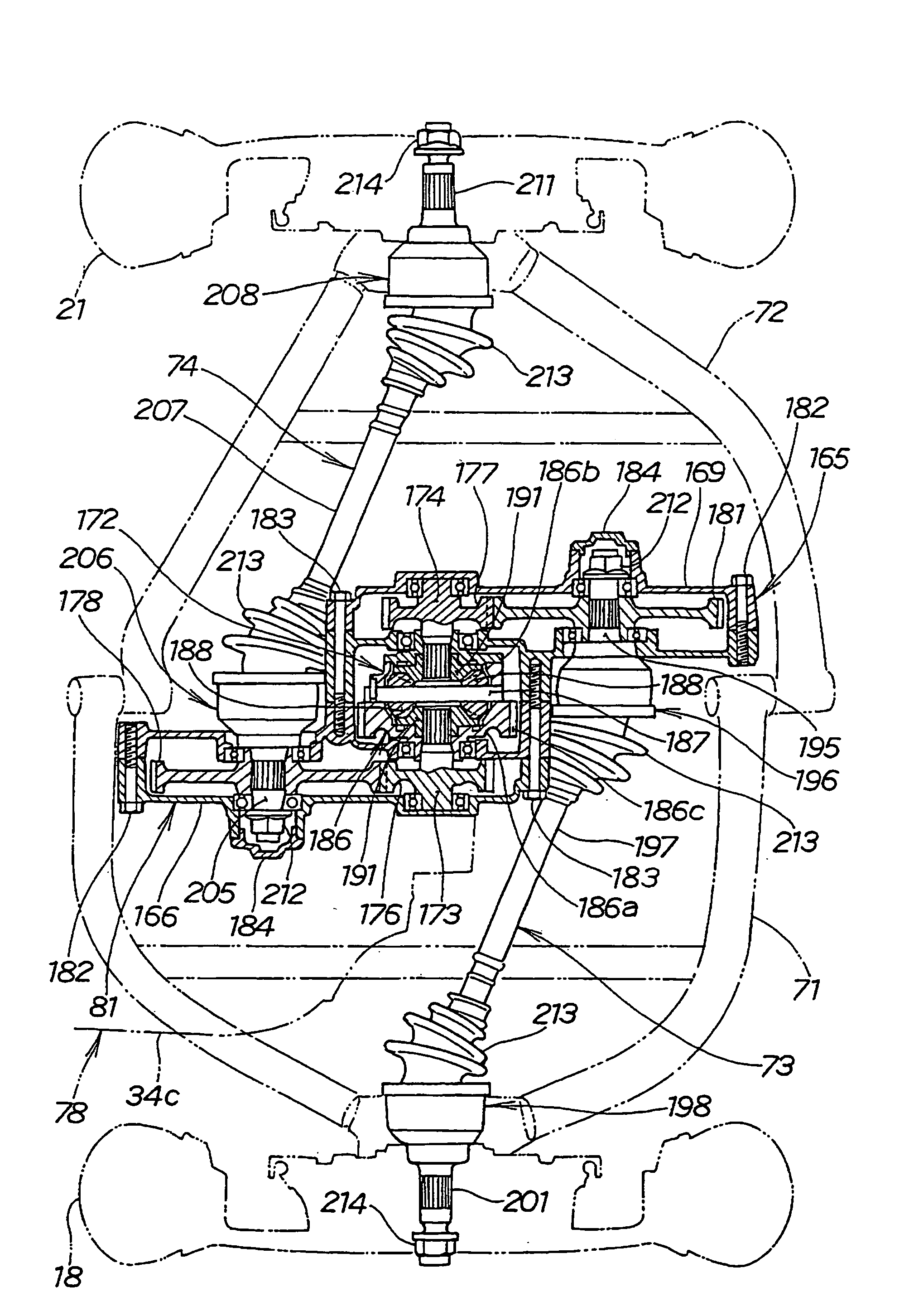
[0018]For example, the right and left output shafts of the reduction gear are directly provided to the right and the left of the reduction gear, a drive shaft extends right and left from these output shafts, the right and left output shafts are provided apart in a longitudinal direction of the body in the invention, compared with a case wherein a wheel is coupled to each end of these drive shafts, the overall length of the drive shaft can be increased if the drive shafts extend diagonally from the right and left output shafts to the side of the wheel and when the rear wheel is vertically moved, an angle of the bend of the drive shaft can be minimized. Further, as the drive shaft diagonally extends even if the overall length is large, the tread of the wheels can be reduced.
[0020]Two shafts on the output side of the differential mechanism can be easily connected to the right and left output shafts via a gear and others.
[0021]It is an object of the present invention to improve a vehicular power transmission mechanism, to enable an easy application of the power transmission mechanism to another vehicle and to greatly reduce the cost of the power transmission mechanism.
[0023]For example, a differential mechanism for a three-wheeled vehicle or a four-wheeled vehicle can be coupled to a unit of an engine and a transmission, respectively, for a motorcycle by attaching the case separate from the crankcase to the crankcase for housing the transmission and housing the differential mechanism in the separate case and the power transmission mechanism can be easily applied. In addition, in the case wherein a speed reducing mechanism, for example, is housed together with the differential mechanism in the case, the speed reducing ratio of a speed reducing mechanism for a three-wheeled vehicle or a four-wheeled vehicle can be freely set according to a type, applying the engine and the transmission for a motorcycle.

Problems solved by technology

Therefore, when the overall length of the drive shaft is short, it is difficult to reduce the angle of the bend.
As a result, the center distance of right and left rear wheels, that is, tread (horizontal distance between the centers of the contact surfaces of the tread of right and left tires with a road surface) is increased, the width of the body is increased and the realization of keeping the angle of the bend at a predetermined angle or less is difficult in a small-sized vehicle.
It damages the mobility of the vehicle to keep the angle of the bend at a predetermined angle or less.
In the case when the power transmission mechanism is applied in another vehicle and applicable vehicles are limited.
As a result, the power transmission mechanism is substantially dedicated and it is difficult to reduce the cost.

Method used


Image

  • Vehicular power transmission mechanism
  • Vehicular power transmission mechanism
  • Vehicular power transmission mechanism

Examples


Embodiment Construction

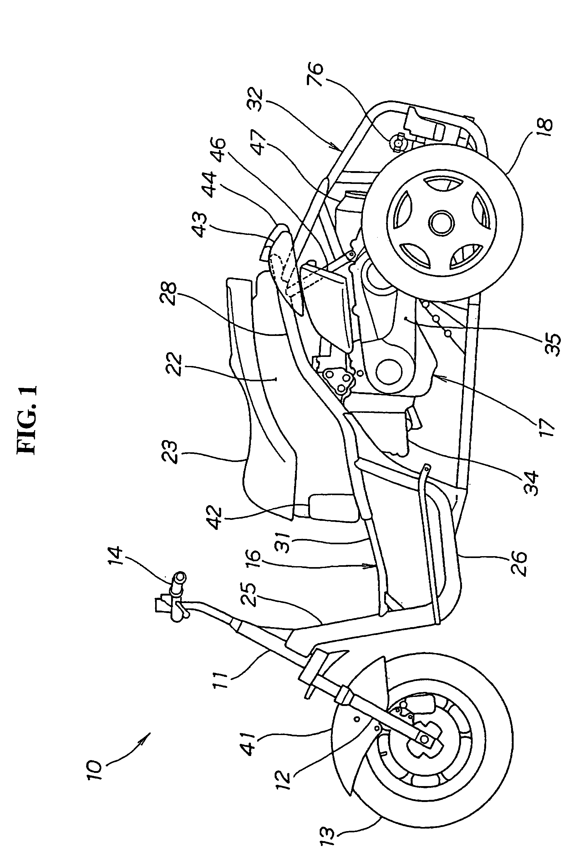
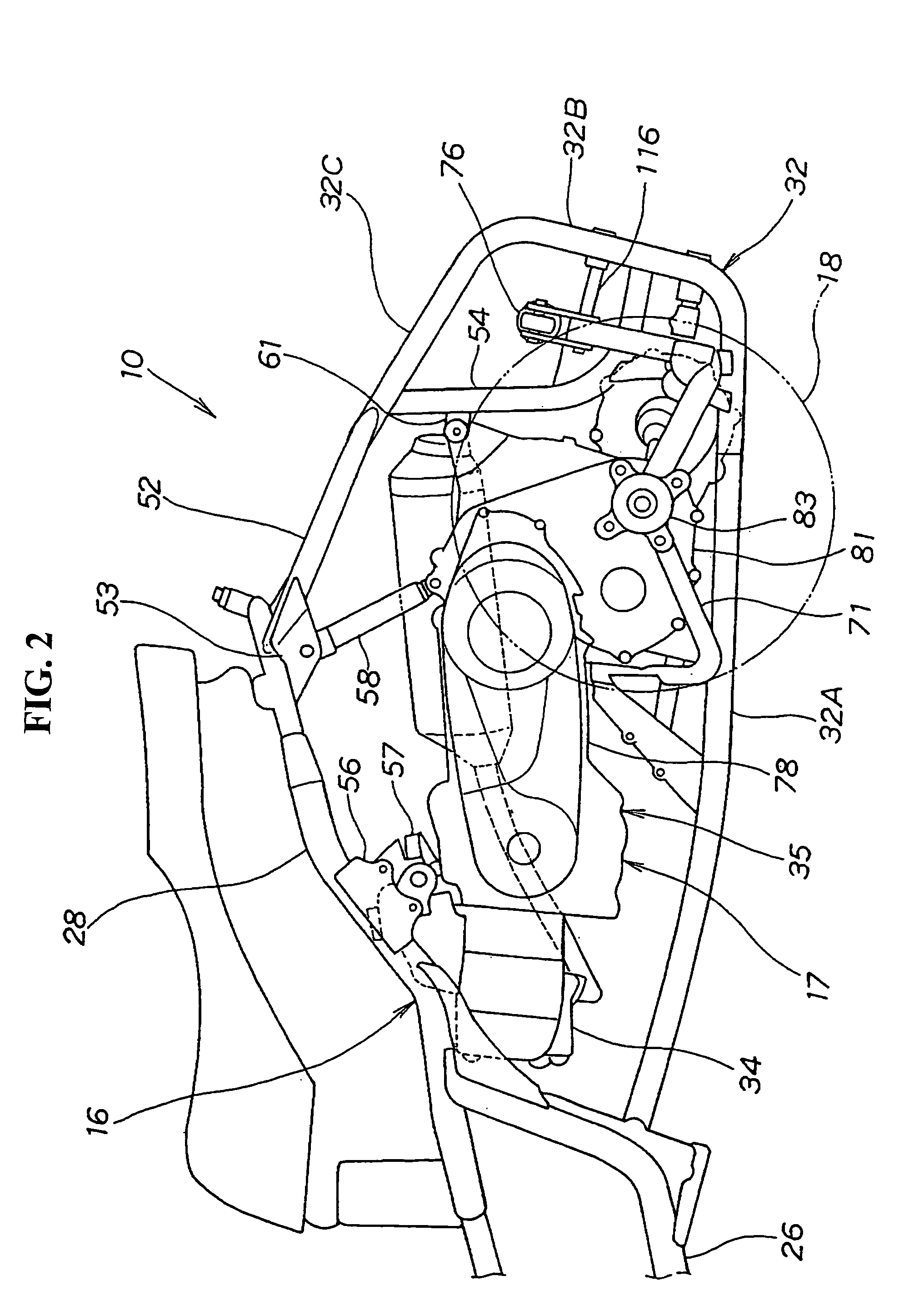
[0051]FIG. 1 is a side view showing a three-wheeled vehicle provided with a swinging mechanism according to the present invention. The three-wheeled vehicle provided with the swinging mechanism 10, hereinafter referred to as the three-wheeled vehicle 10, is composed of a front fork 12 attached to a head pipe 11 so that the front fork can be steered via a handlebar shaft not shown. A front wheel 13 is attached to the lower end of the front fork 12 with a handlebar 14 integrated with the front fork 12. A body frame 16 is attached to the rear of the head pipe 11 with a power unit 17 attached to the rear of the body frame 16. Rear wheels 18, 21 (the rear wheel 21 on the inner side is not shown) are provided as left and right wheels driven by the power unit 17. A housing box 22 is attached to the upside of the body frame 17 and a seat 23 is openably attached to the upside of the housing box 22.

[0052]The body frame 16 is composed of a down pipe 25 extending rearwardly and diagonally downw...


PUM


Abstract

In a three-wheeled vehicle provided with a power transmission mechanism for transmitting the output of an engine to left and right rear wheels via a continuously variable transmission, a gear box and inner shafts of drive shafts as left and right output shafts, the inner shafts which are output shafts of the gear box are provided apart in a longitudinal direction of the body. The overall length of the drive shafts can be increased. When the rear wheel is vertically moved, an angle of the bend of the drive shaft can be minimized. Further, the tread of the wheels can be reduced. Therefore, the width of the body can be reduced and the mobility of the vehicle can be enhanced. In addition, the gear case can be separate from the crankcase and attached to the crankcase with the differential mechanism being housed in the separate gear case.

Description

CROSS-REFERENCE TO RELATED APPLICATIONS[0001]The present application claims priority under 35 USC 119 to Japanese Patent Application No. 2002-369447 filed on Dec. 20, 2002 and Japanese Patent Application No. 2002-373676 filed on Dec. 25, 2002 and the entire contents thereof are hereby incorporated by reference.BACKGROUND OF THE INVENTION[0002]1. Field of the Invention[0003]The present invention relates to a vehicular power transmission mechanism suitable for reducing the tread of rear wheels, keeping an angle of the bend of a drive shaft so that the angle is a predetermined angle or less. In addition, the present invention relates to a vehicular power transmission mechanism which is easily applied to another vehicle and wherein the cost of which can be reduced.[0004]2. Description of Background Art[0005]A power transmission mechanism for a vehicle is known wherein a power transmission mechanism includes concentric right and left axles extending from differential gears to both sides ...

Claims


Application Information

Patent Timeline
IPC IPC(8): B60K17/04B60K17/22B62K5/00B62K5/027B62K5/04B62M7/00
CPCB62K5/027B62K2005/001
Inventor KUROKI, MASAHIROTAKAYANAGI, SHINJI
Owner HONDA MOTOR CO LTD
Learn More