
Suspension system for vehicle and tyre for vehicle

A technology for tires and vehicles, applied in vehicle parts, tire parts, tire tread/tread pattern, etc., to achieve the effect of reducing energy consumption and improving ground contact area

Inactive Publication Date: 2013-06-19
OCIETE DE TECH MICHELIN +1
View PDF4 Cites 0 Cited by
  • Summary
  • Abstract
  • Description
  • Claims
  • Application Information

AI Technical Summary

Problems solved by technology

These solutions, although satisfactory, have now reached their limits, because on the one hand, the material properties have improved, and on the other hand, for the same reasons, the static settings continue to increase

Method used


Image

  • Suspension system for vehicle and tyre for vehicle
  • Suspension system for vehicle and tyre for vehicle
  • Suspension system for vehicle and tyre for vehicle

Examples


Embodiment Construction

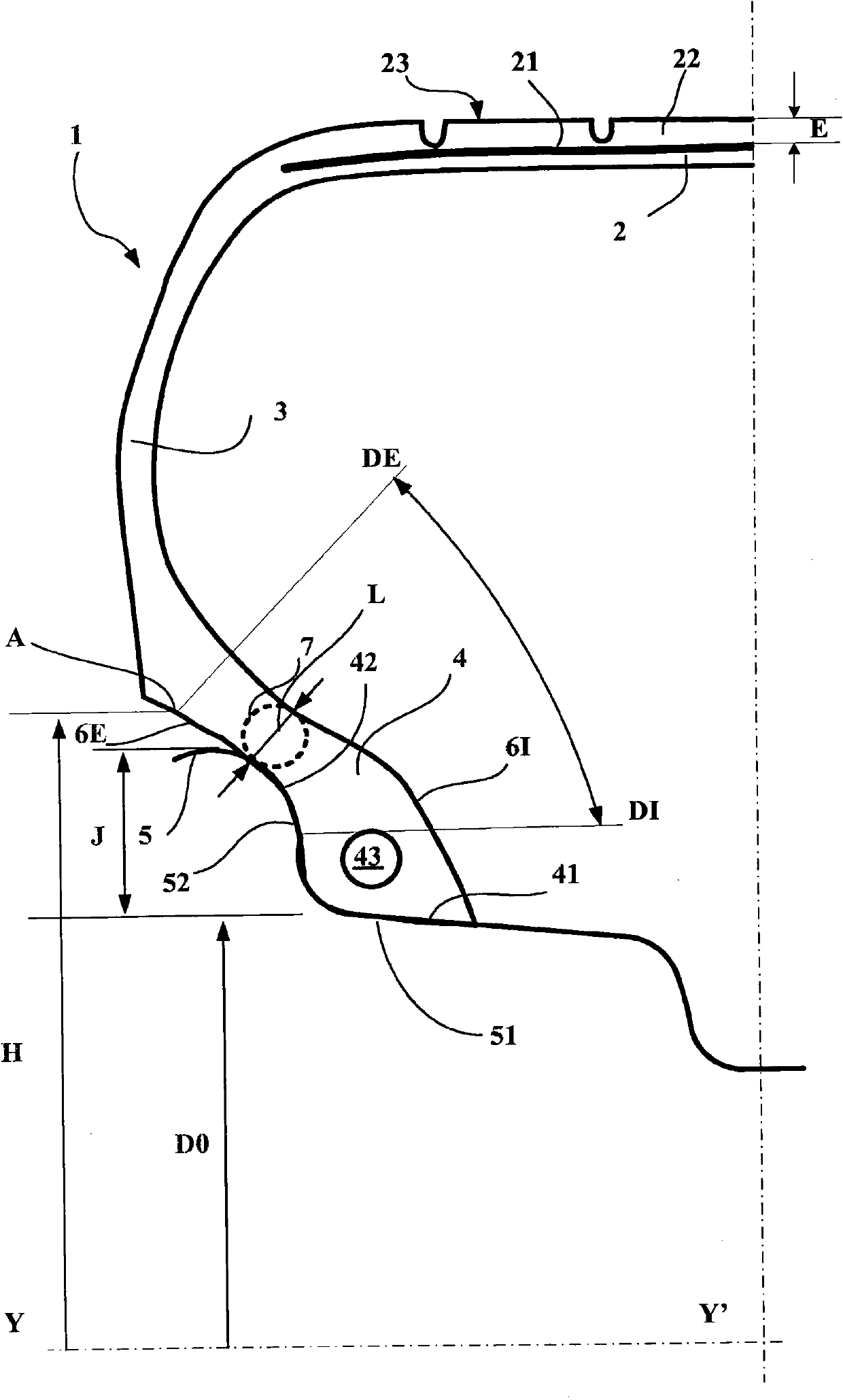
[0028] The single figure attached to this specification shows a partial view of a radial tire 1 used in a combination according to the invention, mounted on a mounting rim 5 and inflated to its normal operating pressure. Seen in a meridian section, ie in a plane containing the axis of rotation (YY'), the tire 1 comprises a bead 4 in contact with a mounting rim 5 extending radially outwards through a sidewall 3 terminating in the There are 2 crown parts.

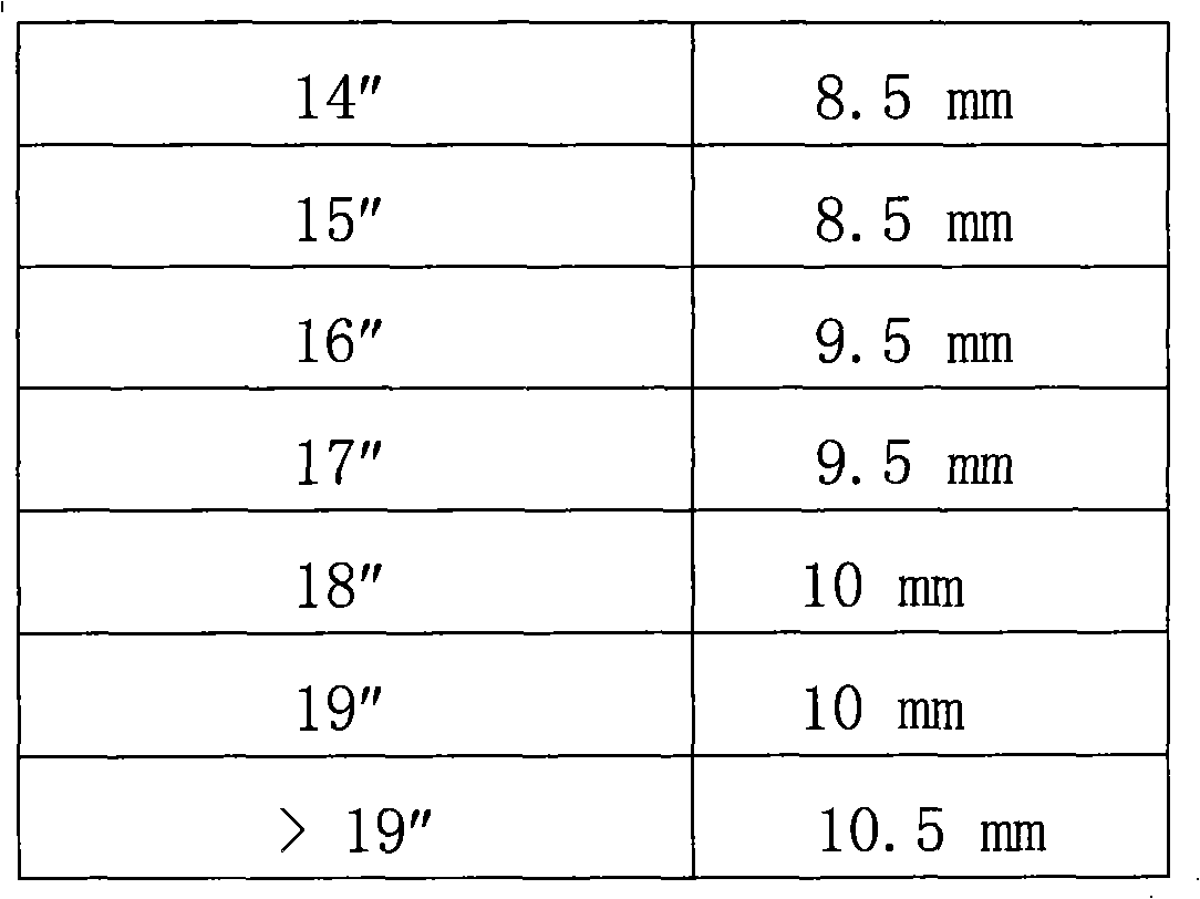
[0029] The mounting rim 5 comprises a seat 51 inclined with respect to the direction of the axis of rotation YY' in order to press the bead seat 41 against it. The rim well 51 extends axially and radially outwards by a rim flange 52 against which the beads of the tire can be pressed. The nominal diameter (Do) of said rim is measured at the point where the rim well and the rim flange intersect according to the provisions of the E.T.R.T.O (European Tire and Rim Technical Organization) standard. The height (J) of the rim flang...


PUM


Abstract

Road-going assembly consisting of a vehicle comprising a front axle and a rear axle, and of a set of tires which are mounted on their mounting rim in order to be fitted to the front axle and the rear axle of this vehicle, the tires of the rear axle having grooves the mean depths of which are at least equal to 3 mm and at most equal to 5 mm, the tires of the front axle having grooves the mean depths of which are greater than 5 mm, this road-going assembly having, at least in the case of the rear axle, static setups (camber, toe-in) of close to zero, that is to say a camber of each wheel-tire assembly on the said axle of between −0.8 degrees and +0.8 degrees and a toe-in at each wheel of between −0.15 degrees and +0.15 degrees, the static setups of the tires of one and the same axle being equal in terms of absolute value and symmetric with respect to a plane perpendicular to the road surface.

Description

technical field [0001] The present invention relates to road running equipment consisting of a passenger vehicle comprising a front axle and a rear axle and a set or set of tires mounted on these axles, and more particularly to a vehicle for achieving enhanced rolling resistance properties without thereby reducing the wear of the tyres. specific assembly conditions required for performance. Background technique [0002] Passenger cars have evolved in this way over the past fifteen years to the same extent, now showing that the overall mass of the rolling assembly has risen and the vehicle's center of gravity has moved further off the ground and further towards the front of the vehicle. This means that there is a significant increase in the difference between the static and dynamic load on the axle, the load moving away from the rear axle with damage to the front axle. The rear axle is now relatively lightly loaded under static conditions and essentially unloaded under braki...

Claims


Application Information

Patent Timeline
Patent Type & Authority Patents(China)
IPC IPC(8): B60C19/00
CPCB60G3/00B60C11/00B60C19/001B60C15/06B60G2200/462B60G9/00B60G2200/4622B60G2200/46Y10S152/904
Inventor F·佩兰N·利维
Owner OCIETE DE TECH MICHELIN
Learn More