Clamp for holding of flat objects

a flat object and clamping technology, applied in the direction of mechanical equipment, other domestic objects, machine supports, etc., can solve the problem that the known clamp is not suitable for pre-assembly or re-assembly

Inactive Publication Date: 2007-04-24
NEWFREY
View PDF18 Cites 29 Cited by
  • Summary
  • Abstract
  • Description
  • Claims
  • Application Information

AI Technical Summary

Benefits of technology

[0003]Clamps of the kind specified are employed for example in automobiles, where they serve to fasten tape lines or films laminated with electric conductors provided to connect electrical apparatus. Here, the problem arises that in some fastening locations, only a single film or a single tape cable is to be held with a clamp, whereas in some other fastening locations, several films and tape cables come together, likewise to be held with one clamp, insofar as possible. Another problem consists in rendering the installation of the lines as simple as possible, one requirement being to pre-assemble clamps and films or lines, the pre-assembled units to be fastened to the substrates provided for the purpose; but another requirement is that it should be possible to introduce additional films or lines into the pre-assembled and ready-installed clamps without impairing the fixation of the films or lines already present. Furthermore, after completion of the installation, there should be a secure fixation of the films or lines in the clamp.
[0007]The clamp according to the invention has the advantage that during assembly, with lid opened to secure the films or tape lines, a low clamping force may be provided, and that in connection with the closing of the lid for lastingly securing the films or tape lines, the clamping force can be enhanced to the desired extent. Additional holding means, such as mandrels engaging holes in the films or tape lines, are therefore not required. Preferably, the lid of the clamp according to the invention comprises a pressure element which, when the lid is closed, exerts a clamping force directed towards the floor of the underpart. The pressure element may consist of an elastically deformable finger attached to the under side of the lid, an opening being provided in the top part through which the finger extends towards the floor of the underpart when the lid is closed. When the lid is opened, the clamping force to secure the films or tape lines is preferably generated by a spring contact pressure element extending between floor and top part in the holding region and attached to the top part or to the underpart. Further, provision may be made so that with the lid closed, the pressure element arranged on it will act on the contact pressure element, so that the latter transmits the clamping force of the pressure element to the films or tape lines.
[0010]Further, provision may be made for the pressure element to have a segment passing through the opening in the interplate, and in contact with the floor of the underpart when the lid is closed, in order to clamp the film arranged on the underpart firmly. Besides, the pressure element may have a segment that rests in contact with the interplate when the lid is closed and clamps the film in the upper holding region. The pressure element may consist, according to the invention, of an arcuate strip of material configured in one piece with the lid, elastically yielding, and thus providing a lasting clamping effect. Alternatively, the pressure element may consist of a body of elastomer material, positively connected to the lid geometrically or materially.

Problems solved by technology

Here, the problem arises that in some fastening locations, only a single film or a single tape cable is to be held with a clamp, whereas in some other fastening locations, several films and tape cables come together, likewise to be held with one clamp, insofar as possible.
Another problem consists in rendering the installation of the lines as simple as possible, one requirement being to pre-assemble clamps and films or lines, the pre-assembled units to be fastened to the substrates provided for the purpose; but another requirement is that it should be possible to introduce additional films or lines into the pre-assembled and ready-installed clamps without impairing the fixation of the films or lines already present.
This known clamp is not suitable for pre-assembly or re-assembly, since after each assembly operation it must be closed completely in each instance in order for the tape cable or cables inserted to be adequately held.

Method used


Image

  • Clamp for holding of flat objects
  • Clamp for holding of flat objects
  • Clamp for holding of flat objects

Examples


Embodiment Construction

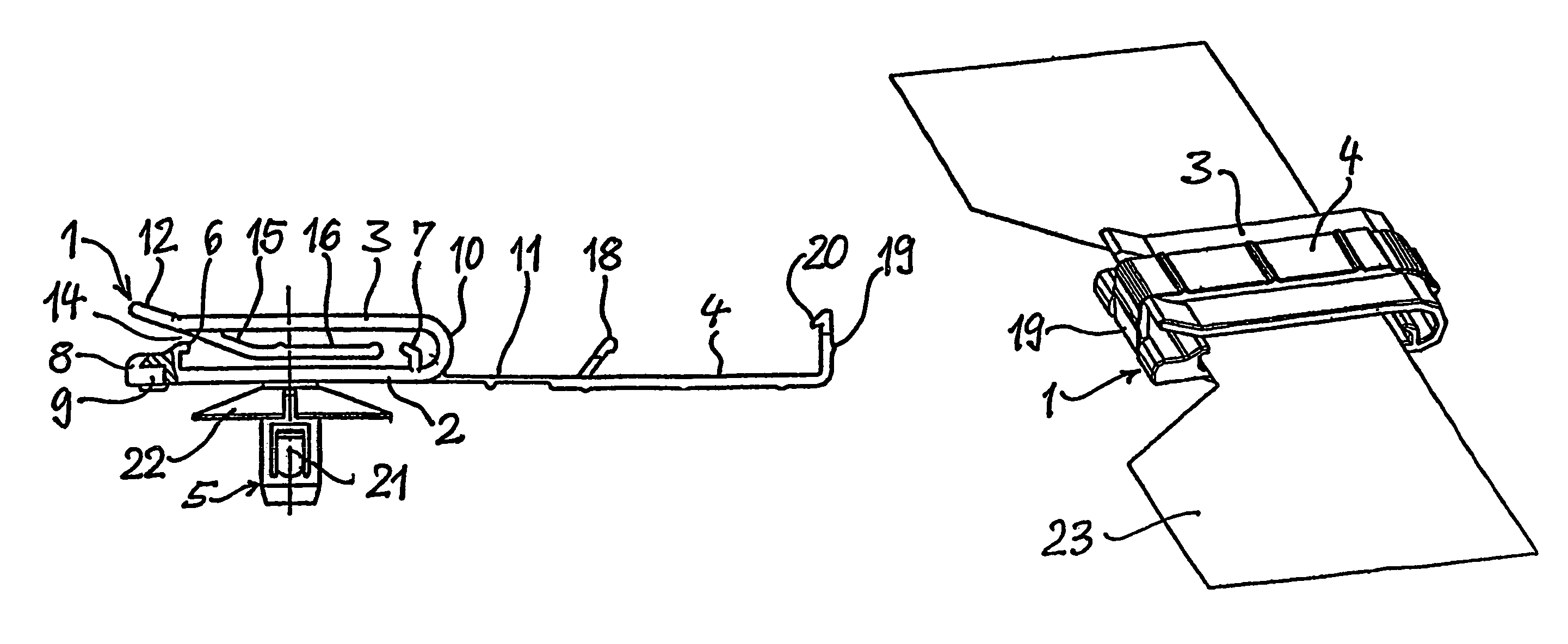
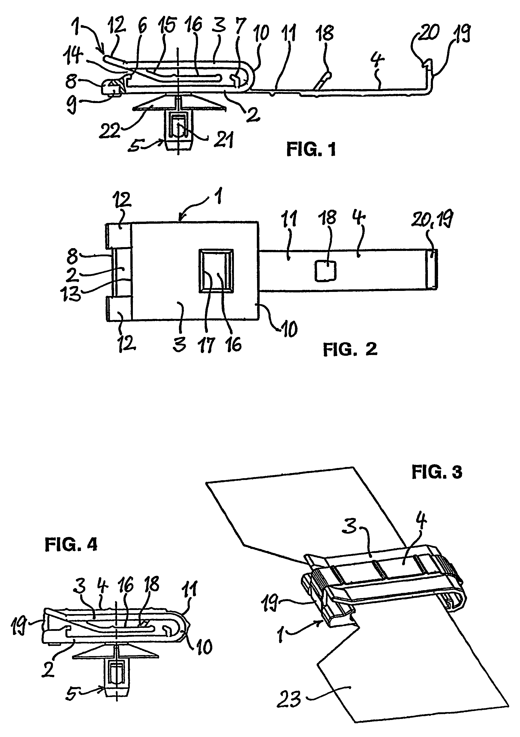
[0020]The clamp 1 shown comprises a plate-like underpart 2, a plate-like top part 3 at a parallel distance therefrom, a strip-like lid 4, and a fastening element 5 connected to the underpart 2. The clamp 1 is made in one piece out of a synthetic material. In departure from this, however, it is possible alternatively to make the fastening element 5 as a separate part, and then connect it to the underpart 2 by suitable means.

[0021]On the bottom of the underpart 2 facing the top part 3, ledge-like stops 6, 7 are configured on the former, located at a parallel distance from each other and serving for lateral bounding of the layer of objects held on the underpart 2, such as films, tape lines or the like. The upper ends of the stops 6, 7 are provided with hooks bent towards each other. The lateral ends of the underpart 2 neighboring upon the stop 6 comprises, in the middle, a recess 8 into which the fastening end of the lid enters. The recess 8 is provided with an undercut 9 on its under ...


PUM


Abstract

A clamp for holding of films, tape lines or the like consists of an underpart consists of a floor and stops projecting from the floor and arranged at a distance from each other, laterally bounding a holding region, and a top part attached to the underpart and opposed to the floor, an entry opening being provided between the top part and the stop arranged on one side of the holding region. The clamp comprises a lid overreaching the top part in closed position and connected to the underpart by a closure, with which lid the entry opening is closable.

Description

CROSS-REFERENCE TO RELATED APPLICATIONS[0001]This application is a continuation of PCT patent application Ser. No. PCT / EP2004 / 009718, filed on Sep. 1, 2004, which claims priority to DE 103 40 571.2, filed on Sep. 1, 2003, both of which are incorporated by reference herein.BACKGROUND AND SUMMARY[0002]The invention relates to a clamp for holding a flat object, such as films, tape lines or the like, which clamp is provided with an underpart comprising a floor and a top part attached to the underpart opposed to the floor, a holding area having an entrance opening being provided between the underpart and the top part.[0003]Clamps of the kind specified are employed for example in automobiles, where they serve to fasten tape lines or films laminated with electric conductors provided to connect electrical apparatus. Here, the problem arises that in some fastening locations, only a single film or a single tape cable is to be held with a clamp, whereas in some other fastening locations, sever...

Claims


Application Information

Patent Timeline
Patent Type & Authority Patents(United States)
IPC IPC(8): F16B15/00F16L3/23
CPCF16L3/23H02G3/32
Inventor ROSEMANN, FRANKHAHN, ERNST LUDWIGSENG, HANS PETER
Owner NEWFREY
Why Eureka
Try Eureka