
Apparatus for supporting airfoils in a grit blasting process

a technology of airfoils and apparatus, which is applied in the direction of grinding machine components, grinding apparatus, grinding machines, etc., can solve the problems of unfavorable small grooves and sharp ridges, and achieve the effect of low manufacturing and maintenance costs and easy loading and unloading of components

Active Publication Date: 2007-04-24
PRATT & WHITNEY CANADA CORP
View PDF15 Cites 12 Cited by
  • Summary
  • Abstract
  • Description
  • Claims
  • Application Information

AI Technical Summary

Benefits of technology

[0007]The apparatus of the present invention is advantageously of low cost for manufacturing and maintenance. The interchangeable component holding member advantageously provides easy loading and unloading of components, with the flexibility to support components of various sizes and profiles. Other features and advantages of the present invention will be better understood with reference to the preferred embodiments described hereinafter.

Problems solved by technology

The varying machining processes result in undesirable small grooves and sharp ridges as metal material around the circumference of the airfoil is removed.

Method used


Image

  • Apparatus for supporting airfoils in a grit blasting process
  • Apparatus for supporting airfoils in a grit blasting process
  • Apparatus for supporting airfoils in a grit blasting process

Examples


Embodiment Construction

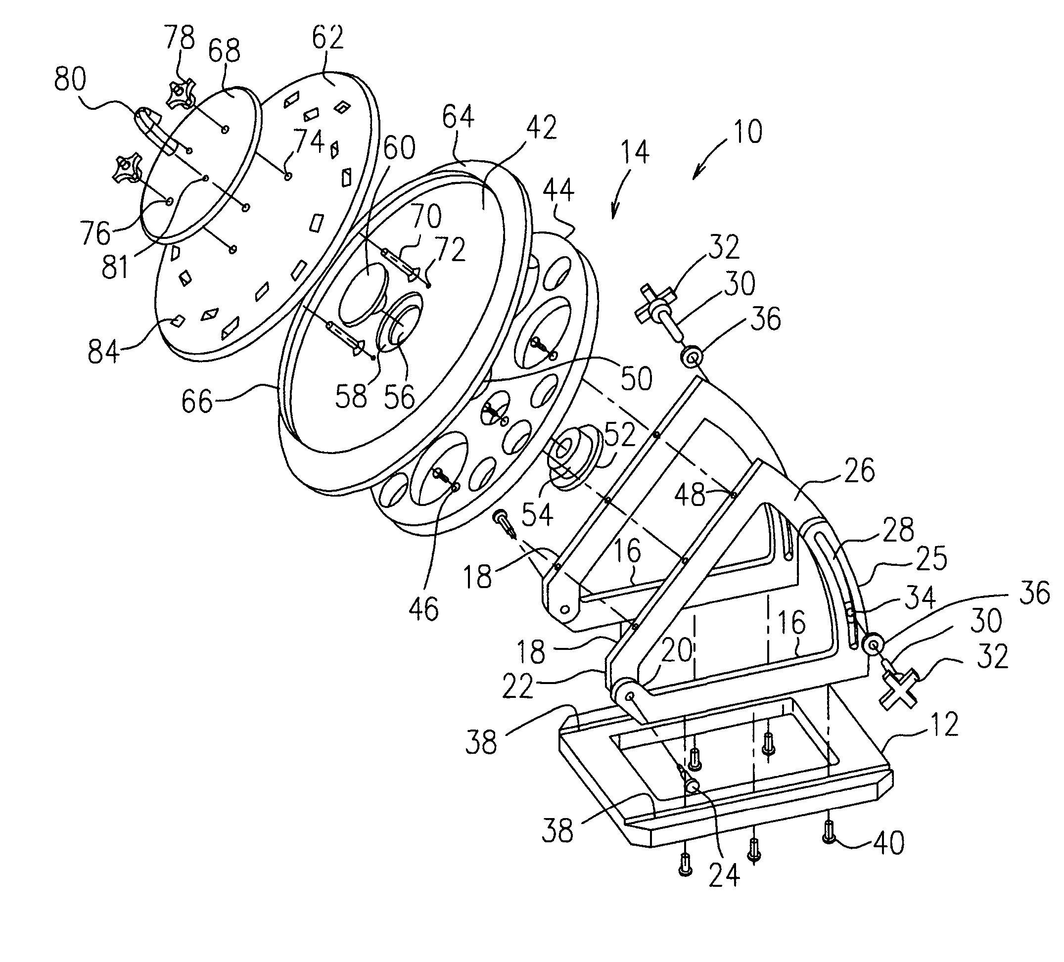
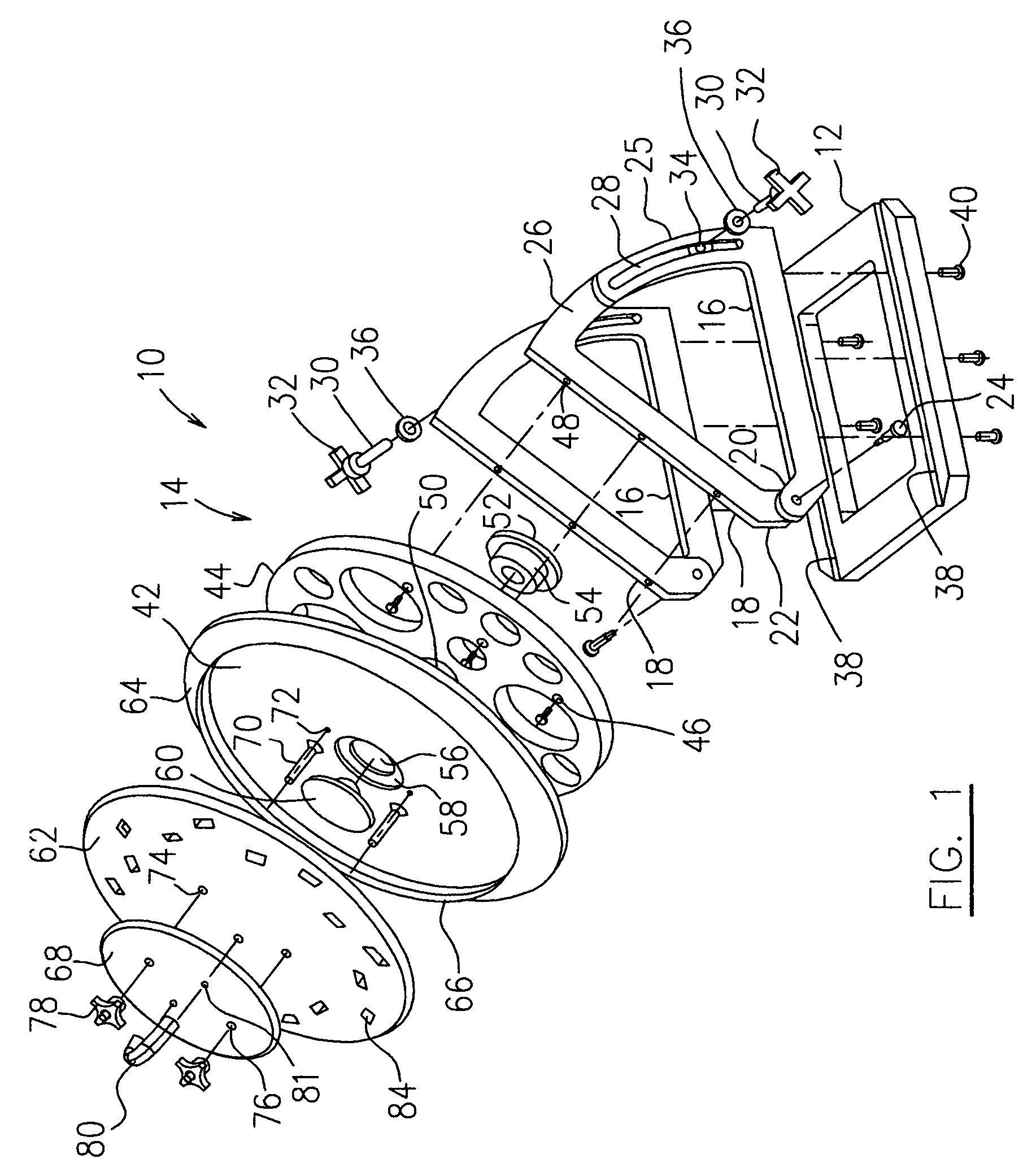
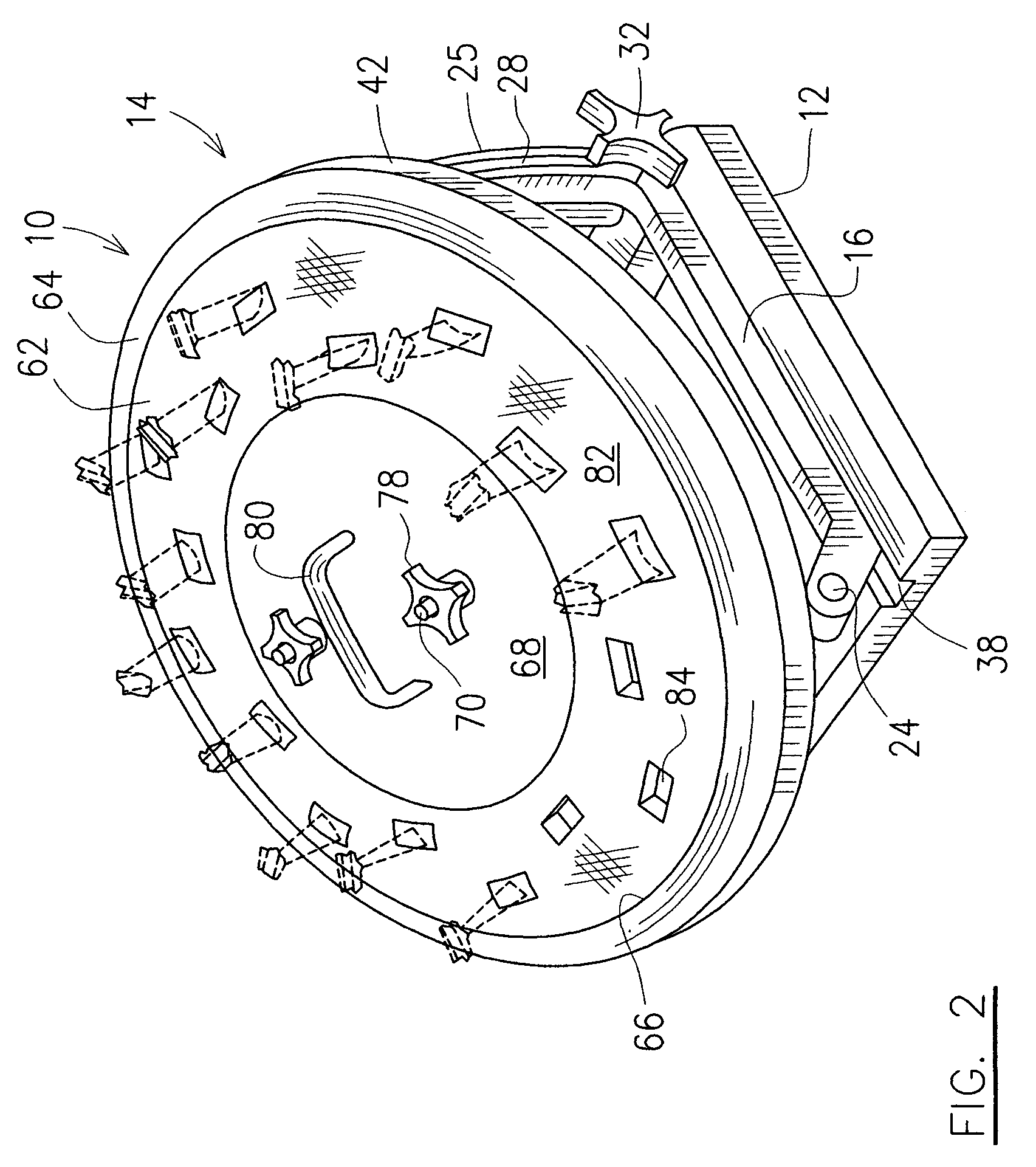
[0012]Referring to FIGS. 1 and 2, an apparatus generally indicated by numeral 10 according to one preferred embodiment of the present invention, includes a base 12 and a platform table assembly 14. The platform table assembly 14 includes at least one, but preferably a pair of bracket assemblies (not indicated) each including first and second bracket members 16 and 18. The bracket members 16, 18 at one end thereof have an end portion 20, 22, respectively, extending angularly and outwardly to be connected together by a bolt or pivot pin 24 such that the second bracket member 18 is pivotable about the pivot pin 24 with respect to the first bracket member 16. The bracket members 16, 18 at the other ends thereof include a curved end portion 25, 26, respectively, extending outwardly towards and overlapping each other such that the first and second bracket members 16, 18 together form an adjustable trianglular support.

[0013]A locking device (not indicated) is provided to lock the first and...


PUM


Abstract

An apparatus provided for supporting at least one component in a grit blasting process comprises a base and a platform table assembly mounted to the base. The platform table assembly includes a platform table therein which is rotatable and angularly adjustable with respect to the base. The platform table includes a component holding device for releasably holding the at least one component in position during the grit blasting process.

Description

FIELD OF THE INVENTION[0001]The present invention relates generally to metal machining processes and more specifically to an apparatus for supporting components in a grit blasting process.BACKGROUND OF THE INVENTION[0002]A gas turbine engine includes various compressor and turbine stator vanes, and rotor blades. The vanes and blades have airfoil profiles specifically configured for use in compressing air or expanding hot combustion gases. The airfoil profiles have three-dimensional contours which vary from root to tip between leading and trailing edges over the opposite pressure and suction sides thereof. The airfoil has a cambered or arcuate curvature between its leading and trailing edges, with the pressure side typically being generally concave and the suction side being generally convex.[0003]The airfoils may be made by various manufacturing processes. The varying machining processes result in undesirable small grooves and sharp ridges as metal material around the circumference ...

Claims


Application Information

Patent Timeline
Patent Type & Authority Patents(United States)
IPC IPC(8): B24C3/20
CPCB24C3/20
Inventor JAMES, JEROME
Owner PRATT & WHITNEY CANADA CORP
Learn More