Rotary type ice maker and method for making ice using the same

a rotary type, ice maker technology, applied in the field of refrigerator ice maker, can solve the problems of reducing requiring a lot of cost and labor in manufacturing the ice maker, and reducing the number of parts of the ice maker, so as to improve the competitiveness of products and reduce the number of parts. , the effect of simple structur

Inactive Publication Date: 2007-05-01
LG ELECTRONICS INC
View PDF7 Cites 32 Cited by
  • Summary
  • Abstract
  • Description
  • Claims
  • Application Information

AI Technical Summary

Benefits of technology

[0021]Accordingly, it is an object of the invention to provide a rotary type ice maker and a method for making ice using the ice maker, wherein the ice cubes can be separated by their own weight by rotating an ice making mold in which water is frozen into the ice cubes, whereby several additional components for releasing the ice cubes are not required and also price competitiveness of products can be secured by a reduction of the number of parts thereof.
[0026]That is, the rotary type ice maker having the above constitution can separate the ice cubes by rotating the ice making mold itself. Thus, the ice maker of the invention can be embodied as a simple structure without additional components such as the ejector, the stripper, and so on in the prior art.
[0027]Thus, according to a rotary type ice maker of the present invention, since additional devices for ejecting the ice cubes are not required, the number of parts of the ice maker can be reduced. Accordingly, price competitiveness of products can be secured by a reduction of the number of parts thereof and a reduction of the material cost. Further, a decrease of the heat quantity spent in releasing the ice cubes can be conducive to the temperature maintenance of the refrigerator, thereby improving an ice making performance of the ice maker.

Problems solved by technology

Thus, there have been several drawbacks in that price competitiveness of products was lowered due to many components for the ice maker 105 and also maintenance and repairs of the ice maker 105 were difficult.
However, because the means for rotating the double-sided ice cube tray 202 is complicatedly constructed in the ice maker 200, a lot of cost and labor is required in manufacturing of the ice maker 200.
As a result, the maintenance and repairs of the ice maker 200 were difficult, and price competitiveness of products was lowered due to the expensive unit cost of parts for the rotating means.

Method used


Image

  • Rotary type ice maker and method for making ice using the same
  • Rotary type ice maker and method for making ice using the same
  • Rotary type ice maker and method for making ice using the same

Examples


second embodiment

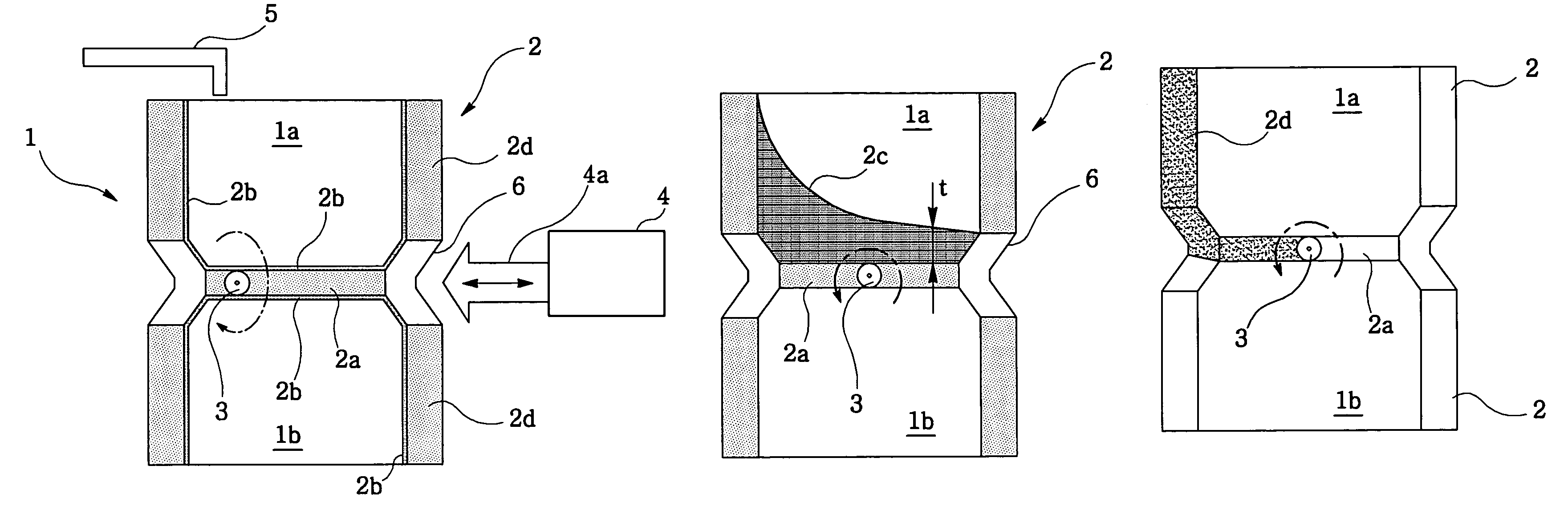
[0051]FIG. 9 shows an ice making mold 2 according to the present invention. The ice making mold 2 comprises an upper mold having a plurality of upper ice making cavities 1a opened upwardly and a lower mold a plurality of lower ice making cavities 1b opposite to the upper ice making cavities 1a.

[0052]A rotating shaft 3 is inserted in the bottom wall 2a of the ice making mold 2 to support the ice making mold 2 and located at the center of the width thereof. To give a self-rotation to the ice making mold 2 by its own weight or by the weight of ice cubes in the upper ice making cavities 1a, the ice making mold 2 has the bottom wall 2a of thickness ‘t’ formed in such a manner that the thickness ‘t’ gradually increases from one side to the other side of the bottom wall 2a.

third embodiment

[0053]FIG. 10 shows an ice making mold 2 according to the present invention. The ice making mold 2 comprises an upper mold having a plurality of upper ice making cavities 1a opened upwardly and a lower mold having a plurality of lower ice making cavities 1b opposite to the upper ice making cavities 1a.

[0054]A rotating shaft 3 is inserted in the bottom wall 2a of the ice making mold 2 to support the ice making mold 2 and located at the center of the width thereof. To give a self-rotation to the ice making mold 2 by its own weight or by the weight of ice cubes in the upper ice making cavities 1a, the one sidewall 2d of the ice making mold 2 is made of heavier material than that of the opposite sidewall in its own specific weight. The weight unbalance between the opposite sidewalls causes the ice making mold 2 to be self-rotated and reversed.

[0055]Method of making ice according to the present invention will be described hereinbelow with reference to FIG. 11.

[0056]Method of making ice ...


PUM


Abstract

Disclosed are a rotary type ice maker and a method for making ice using the same. The rotary type ice maker comprises an ice making mold having ice making cavities in upper and lower sides thereof, respectively, a rotating shaft for supporting the ice making mold so that the ice making mold is rotated by its own weight or by the weight of ice cubes in the ice making cavities, and a mold position fixing device for fixing or releasing the ice making mold by engaging with the ice making mold or separating from the ice making mold.

Description

FIELD OF THE INVENTION[0001]This invention generally relates to an ice maker of a refrigerator, where water is frozen into ice cubes, and more particularly, to a rotary type ice maker and a method for making ice using the ice maker, wherein ice cubes can be removed by their own weight by reversing an ice making mold in which water is frozen into the ice cubes, whereby several components for making the ice cubes are not required and also the cost of production can be lowered by a reduction of the number of parts thereof.BACKGROUND OF THE INVENTION [0002]Generally, an ice maker comprises an ice making mold with a plurality of ice making cavities containing water therein to be frozen by cold air generated from a freezer of a refregerator and making water into ice cubes.[0003]As shown in FIG. 1, a conventional refrigerator having a freezing compartment F and a refrigerating compartment R therein, which are divided each other by a barrier 101, comprises a body 102 in which a refrigeratin...

Claims


Application Information

Patent Timeline
Patent Type & Authority Patents(United States)
IPC IPC(8): F25C1/10
CPCF25C1/10F25C5/08F25C2305/022F25C2305/0221F25C5/02
Inventor YANG, HO NAM
Owner LG ELECTRONICS INC
Why Eureka
Try Eureka