Warning light control method

a technology of warning light and control method, which is applied in the direction of electrical equipment, etc., can solve the problems of increasing the manufacturing cost, poor warning effect, and increasing the sales price of the light device terminal, so as to improve the stability of the warning light control and the coordination of flashing, reduce the manufacturing cost of the light device, and improve the effect of price competitiveness

Active Publication Date: 2022-09-20
ESUSE AUTO PARTS MFG
View PDF2 Cites 0 Cited by
  • Summary
  • Abstract
  • Description
  • Claims
  • Application Information

AI Technical Summary

Benefits of technology

[0004]The present invention has been accomplished under the circumstances in view. It is therefore the main object of the present invention to provide a warning light control method, which includes the following steps: accept multiple warning lights to receive a start command to set up a Flash Mode and number each warning light sequentially starting from 1, and use the Flash Mode number to synchronously set the ID Number of each warning light; set the ID Number of one predetermined warning light as a Starter and the remaining ID Numbers as Receivers; the warning light set as Starter receives a start command signal from the Control Bus through the cable thereof, and sends a Data, a Clock Pulse and an ID Information from the Data Bus, and selects one for flashing by the Flash Mode; the warning lights set as Receivers get the Data, the Clock Pulse and the ID Information from the Data Bus through the cables thereof, and the warning lights of the Receivers and the Starter are flashing synchronously or asynchronously; whether the common Control Bus of the Starter and the Receivers has received a Change ID Command. Through the aforementioned Light Device control steps, set each warning light to have its ID Number. The Starter transmits data, clock and identity signals through the Data Bus to control multiple Receivers, without the need to set up an electronic control device to control the flashing mode of multiple warning lights. At the same time, it can improve the stability of the warning light control and the coordination of flashing, and can reduce the manufacturing cost of the light device, which will help the price competitiveness in the sales market.

Problems solved by technology

However, the flashing effect of multiple warning lights controlled by an electronic control device is not very coordinated, and it also causes the warning effect to be poor.
In addition, the additional electronic control device in the market light device also increases the manufacturing cost, and the sales price of the light device terminal also increases, which is not conducive to the price competitiveness in the sales market.

Method used


Image

  • Warning light control method
  • Warning light control method
  • Warning light control method

Examples


Embodiment Construction

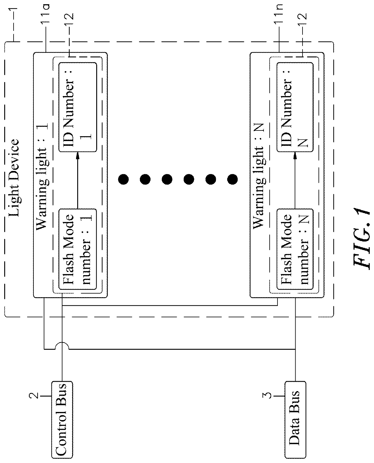
[0020]Referring to FIGS. 1-3 and 5-6, the Light Device control architecture of the present invention comprises a Light Device 1, a Control Bus 2 and a Data Bus 3. Its main component and features are detailed as follows:

[0021]Referring to FIG. 1, the Light Device 1 comprises a plurality of warning lights (11a˜11n), and each of these warning lights (11a˜11n) is electrically connected to the Control Bus 2 and the Data Bus 3 through a cable. These warning lights (11a˜11n) each have built therein an EEPROM 12. Each of the warning lights (11a˜11n) comprises a PCB (not shown), and a plurality of LEDs (not shown), at least one EEPROM 12, and a plurality of Pads (not shown) for electrical connection of a plurality of cables are arranged on the PCB.

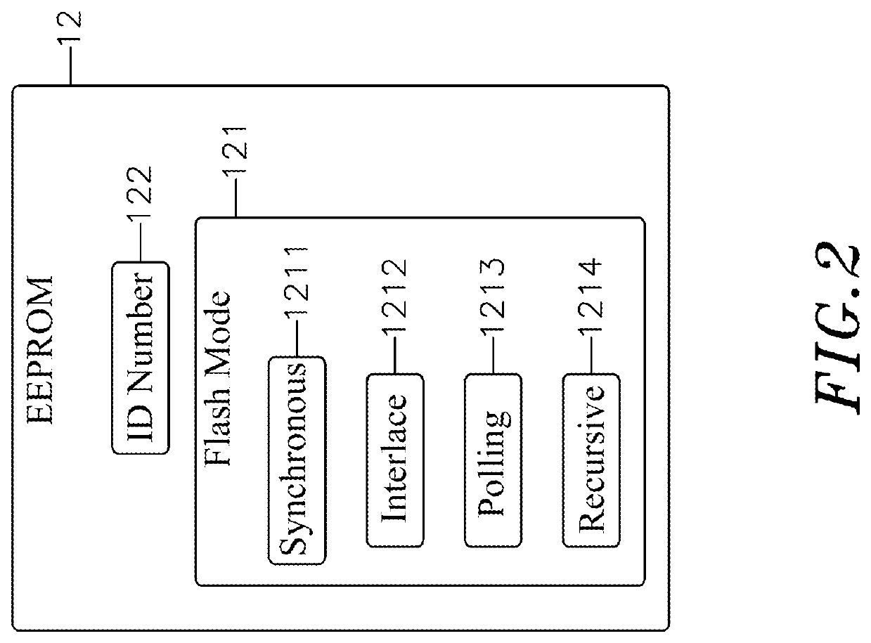
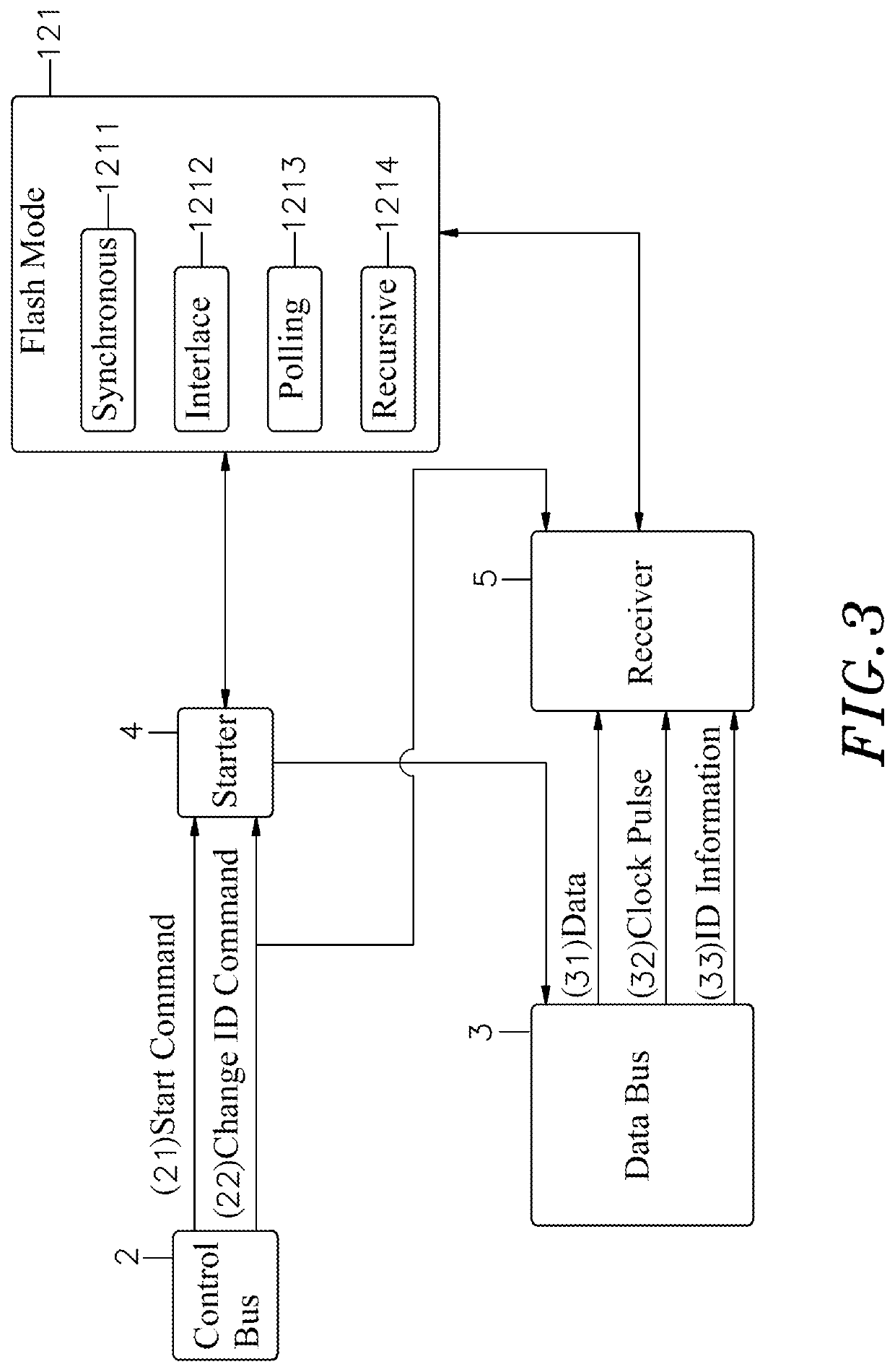
[0022]Referring to FIG. 2, the EEPROM 12 of each of the warning lights (11a˜11n) has stored therein a Flash Mode 121 and an ID Number 122. The Flash Mode 121 includes Synchronous 1211, Interlace 1212, Polling 1213 and Recursive 1214.

[0023]In additi...


PUM


Abstract

A warning light control method includes the steps of: accepting multiple warning lights to receive a start command to set up Flash Mode and numbering each warning light sequentially starting from 1, and using Flash Mode number to synchronously set ID Number of each warning light; setting the ID Number of a predetermined warning light as Starter and the remaining ID Numbers as Receivers; the warning light of Starter receiving Start Command from Control Bus through cable, and sending Data, Clock Pulse and ID Information from Data Bus, and selecting one for flashing by Flash Mode; warning lights of Receivers get Data, Clock Pulse and ID Information from Data Bus through cables thereof, and warning lights of Receivers and Starter are flashing synchronously or asynchronously; whether Control Bus of Starter and Receivers has received Change ID Command.

Description

[0001]This application claims the priority benefit of Taiwan patent application number 110106770, filed on Feb. 25, 2021.BACKGROUND OF THE INVENTION1. Field of the Invention[0002]The present invention relates to warning light control technology, and more particularly to a warning light control method, which sets an ID Number for each warning light, enables the Starter to transmit data, clock and identity signals through the Data Bus to control multiple Receivers, without the need for an additional electronic control device to control the flashing mode of multiple warning lights. It can improve the stability of the warning light control and the coordination of flashing, and can reduce the manufacturing cost of the light device, which will help the price competitiveness in the sales market.2. Description of the Related Art[0003]Warning lights are used in many environments and places, such as road construction warnings, public places safety warnings, high-rise building safety warnings,...

Claims


Application Information

Patent Timeline
Patent Type & Authority Patents(United States)
IPC IPC(8): H05B47/16H05B47/155
CPCH05B47/16H05B47/155H05B47/18
Inventor LEE, TING-FANGHAN, WEN-CHUNG
Owner ESUSE AUTO PARTS MFG
Why Eureka
Try Eureka