Eureka AIR delivers breakthrough ideas for toughest innovation challenges, trusted by R&D personnel around the world.

Automated-feed surgical clip applier and related methods

Active Publication Date: 2007-05-01
TELEFLEX MEDICAL INC
View PDF39 Cites 1287 Cited by
  • Summary
  • Abstract
  • Description
  • Claims
  • Application Information

AI Technical Summary

Benefits of technology

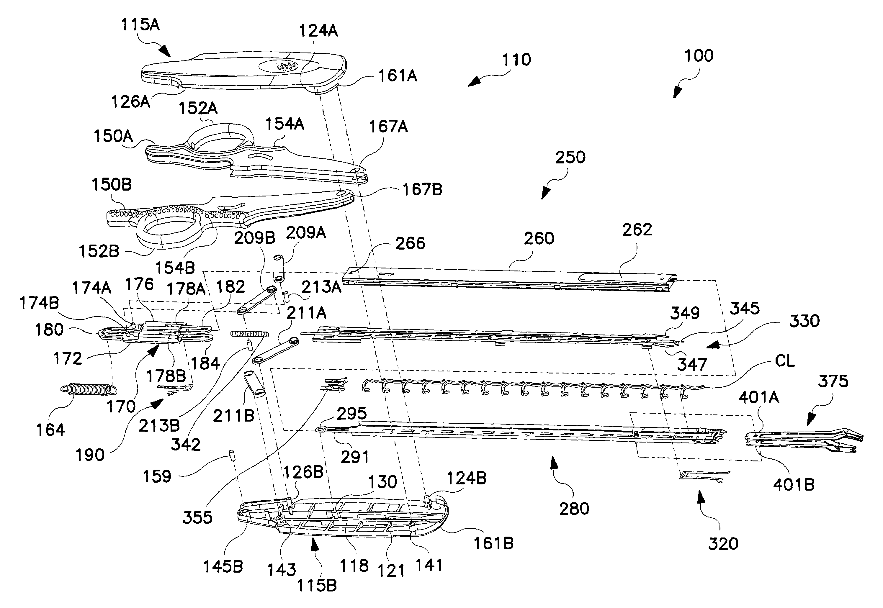
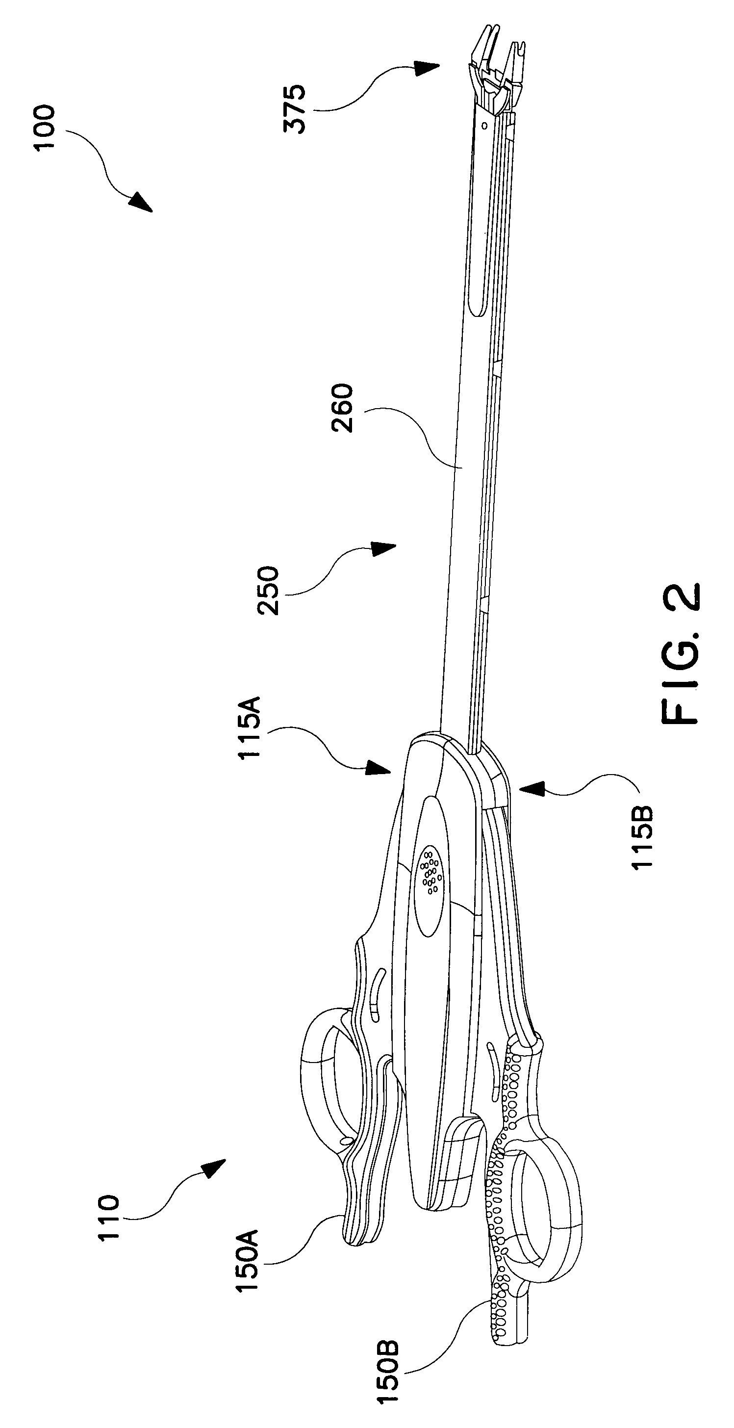
[0013]In general terms, the present invention provides an automated-feed clip applying instrument that is advantageously employed to manipulate surgical clips such as ligating clips, and especially polymeric, latchable clips of asymmetric design such as those described herein by way of example. Clip appliers provided according to embodiments of the present invention comprise an actuating section, a jaw section, and an elongate section between the actuating and jaw sections. Clips are stored in the elongate section and advanced along the length thereof in response to actuating events caused by operation of the actuating section by the user. The elongate section is designed to store the clips in a serial arrangement, and in a manner that keeps the clips stabilized as they are advanced in an indexing fashion towards the jaw section. As described in more detail below, certain features of the invention allow the clips to be stacked closer together than heretofore possible, thereby permitting a shorter elongate section to be employed. Moreover, the invention provides a clip control system that enables a unique clip loading preparation sequence, in which each clip is advanced toward a distal end of the elongate section and rotated to a position optimal for subsequently loading the clip into the jaw section.
[0014]In another aspect, the invention provides a stroke control system that enhances the user's control over the clip applier as well as over a clip loaded in its jaw section, and improves the user's ability to approximate the clip prior to latching the clip to a target tissue. The stroke control system enables the forward stroke of the clip applier to be executed in two separate stages. Both stages are fully controllable by the user through manipulation of the actuating section. During the first stage, all clips stored in the elongate section are advanced along its length, the most distal clip is loaded into the jaw section, and other clips immediately following the most distal clip are prepared for controlled loading into the jaw section in anticipation of subsequent clip applications. During the second stage, the user can repeatedly actuate the jaw section to partially compress and reposition the clip loaded in the jaw section until that clip is ready to be applied. The invention enables such adjustment or approximation of the clip to be accomplished without applying the clip, and without advancing other clips through the elongate section or loading other clips into the jaw section. Once the user determines that the clip loaded in the jaw section is ready to be applied, the user completes the second stage of the forward stroke by operating the actuating section to fully actuate the jaw section. The return stroke is then executed without affecting the remaining clips stored in the clip applier.

Problems solved by technology

The use of surgical thread for ligation requires complex manipulations of the needle and suture material to form the knots required to secure the vessel.
Such complex manipulations are time-consuming and difficult to perform, particularly in endoscopic surgical procedures that afford limited space and visibility.
With the advent of high technology diagnostic techniques using computer tomography (CATSCAN) and magnetic resonance imaging (MRI), metallic clips have been found to interfere with the imaging techniques.
Unlike metallic clips, which are usually symmetric, polymeric clips are usually asymmetric in design and hence lack an axis of symmetry.

Method used


Image

  • Automated-feed surgical clip applier and related methods
  • Automated-feed surgical clip applier and related methods
  • Automated-feed surgical clip applier and related methods

Examples


Embodiment Construction

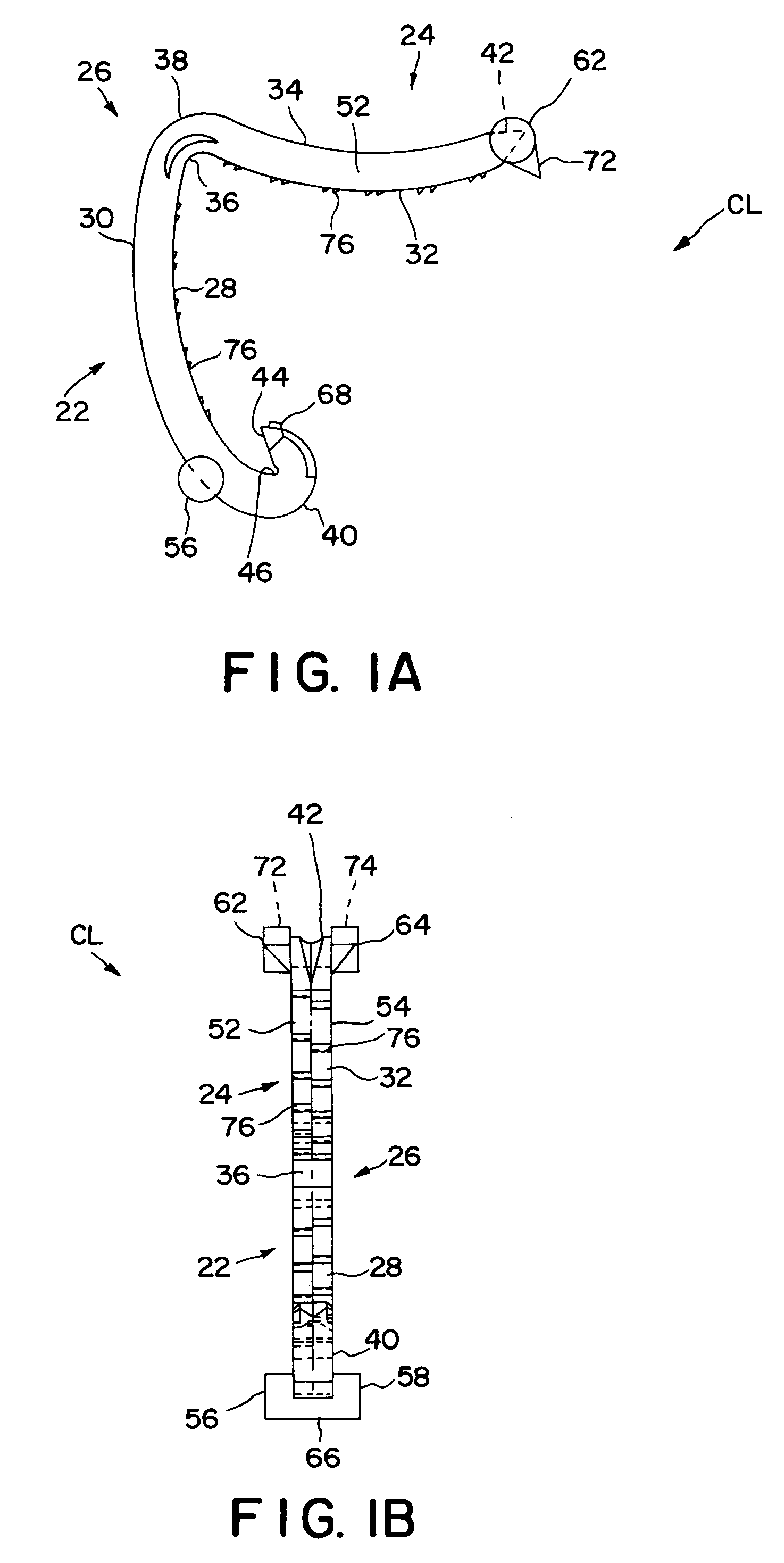
[0052]The clip applier of the present invention as described in detail below is particularly designed for use in manipulating a polymeric, asymmetric clip that is movable into a closed, latched state when clamped onto tissue. An example of this type of clip, generally designated CL, is illustrated in FIGS. 1A and 1B. Clip CL preferably comprises a one-piece integral polymeric body formed from a suitable strong, biocompatible engineering plastic such as the type commonly used for surgical implants. Examples include polyethylene terephthalate (PET), polybutylene terephthalate (PBT), polyoxymethylene, or other thermoplastic materials having similar properties that can be injection-molded, extruded or otherwise processed into like articles.

[0053]The body of clip CL comprises a first or outer leg, generally designated 22, and a second or inner leg, generally designated 24. First and second legs 22 and 24 are joined at their proximal ends by an integral hinge or heel section, generally de...


PUM


Abstract

A surgical clip applying apparatus comprises an actuator device, a ratchet mechanism, a locking mechanism, and a clip driving device. The actuator device comprises an interior and a cam mechanism disposed therein. The cam mechanism comprises an axial cam surface. The locking mechanism is movable by the actuator device within the interior in a distal direction and in a proximal direction. While moving in the distal direction, the locking mechanism contacts the axial cam surface, thereby causing the locking mechanism to engage the ratchet mechanism to limit movement of the locking mechanism in the proximal direction. Continued movement of the locking mechanism in the distal direction causes the locking mechanism to move off the axial cam surface, thereby enabling the locking mechanism to bypass the ratchet mechanism during a return stroke.

Description

TECHNICAL FIELD[0001]The present invention generally relates to surgical clip applying instruments and their use in manipulating clips in surgical procedures such as vessel ligation. More particularly, the present invention relates to a clip applier particularly adapted for manipulating polymeric asymmetric clips and sequentially feeding such clips in an automated manner.BACKGROUND ART[0002]Many surgical procedures require vessels or other tissues of the human body to be ligated during the surgical process. For example, many surgical procedures require cutting blood vessels (e.g., veins or arteries), and these blood vessels may require ligation to reduce bleeding. In some instances, a surgeon may wish to ligate the vessel temporarily to reduce blood flow to the surgical site during the surgical procedure. In other instances a surgeon may wish to permanently ligate a vessel. Ligation of vessels or other tissues can be performed by closing the vessel with a ligating clip, or by suturi...

Claims


Application Information

Patent Timeline
IPC IPC(8): A61B17/10A61B17/068A61B17/122A61B17/128
CPCA61B17/068A61B17/1285A61B17/122A61B2090/08021
Inventor HUGHETT, J. DAVID
Owner TELEFLEX MEDICAL INC
Why Eureka
Eureka Blog
Learn More