Device for applying a horizontal paper border on a wall

Inactive Publication Date: 2007-05-08
BREWER ROBERT F +1
View PDF7 Cites 5 Cited by
  • Summary
  • Abstract
  • Description
  • Claims
  • Application Information

AI Technical Summary

Benefits of technology

[0009]The border paper can be easily mounted by a single person in a job that can be completed i

Problems solved by technology

One of the problems with attaching a paper border on a wall is that normally the entire length of paper is soaked in wat

Method used


Image

  • Device for applying a horizontal paper border on a wall
  • Device for applying a horizontal paper border on a wall
  • Device for applying a horizontal paper border on a wall

Examples


Embodiment Construction

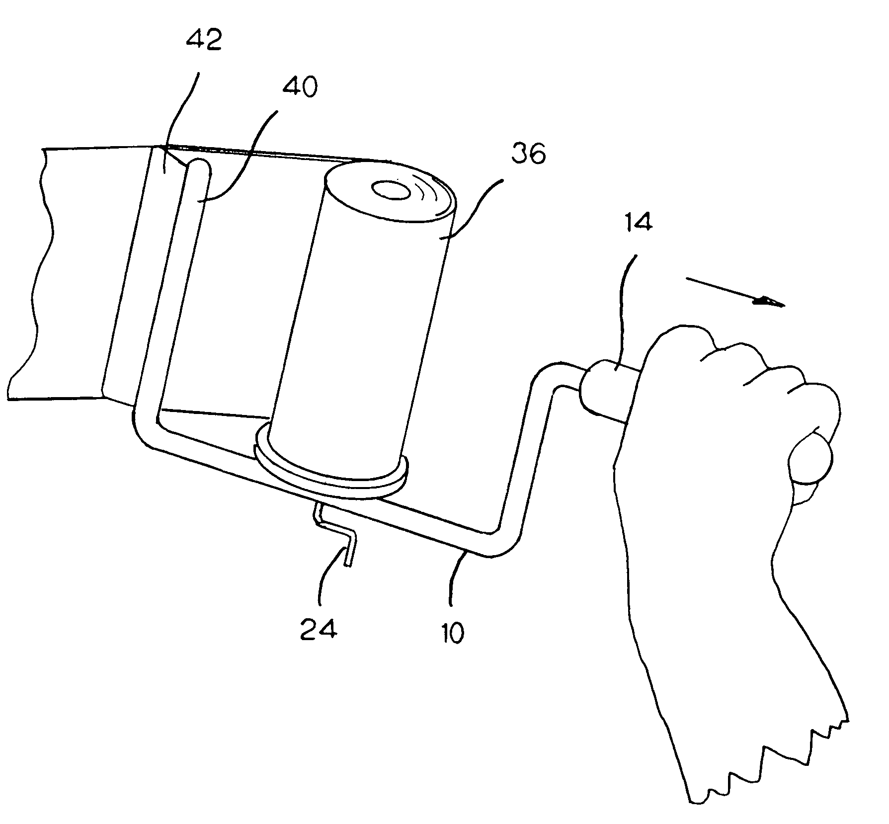
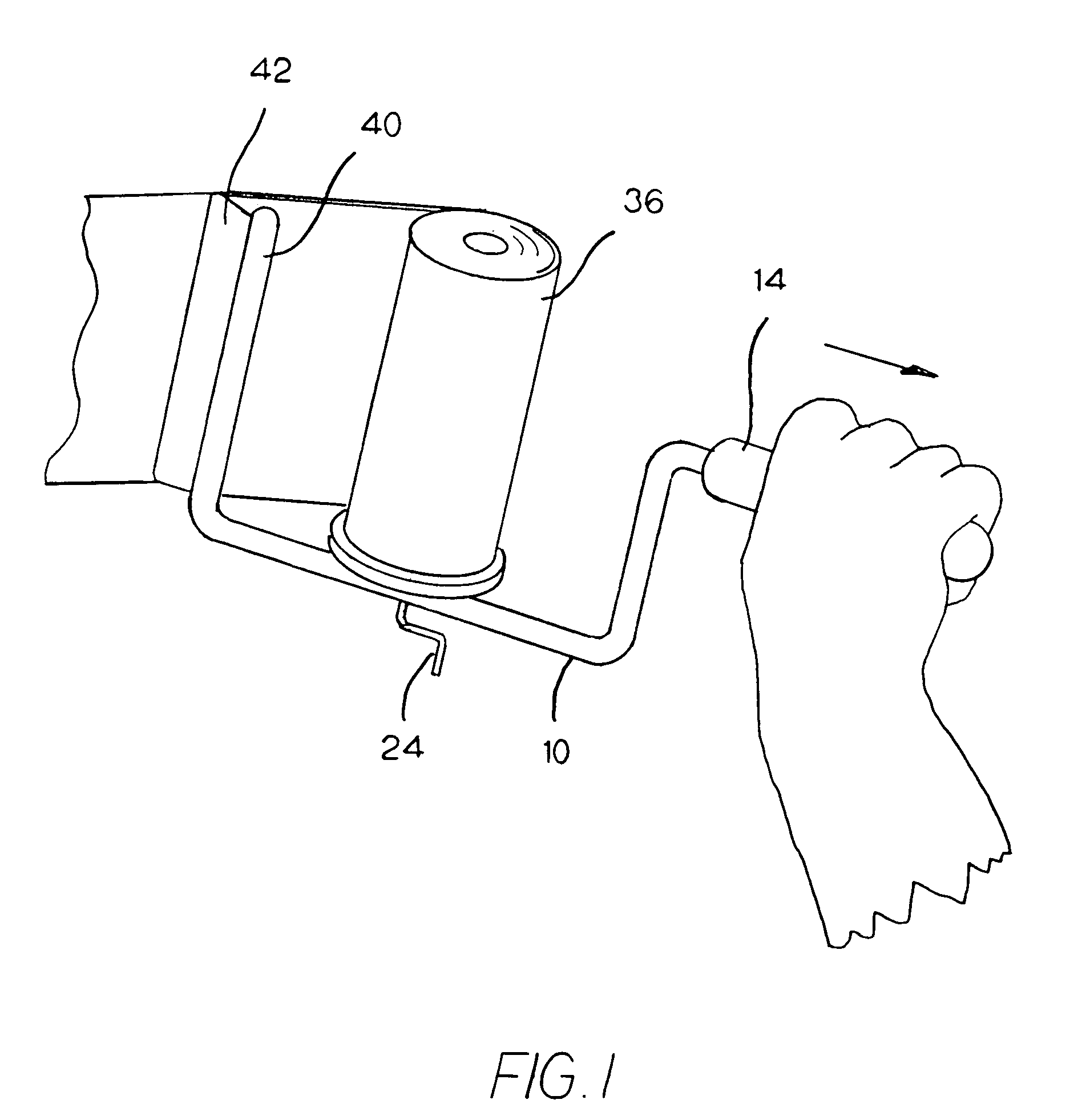
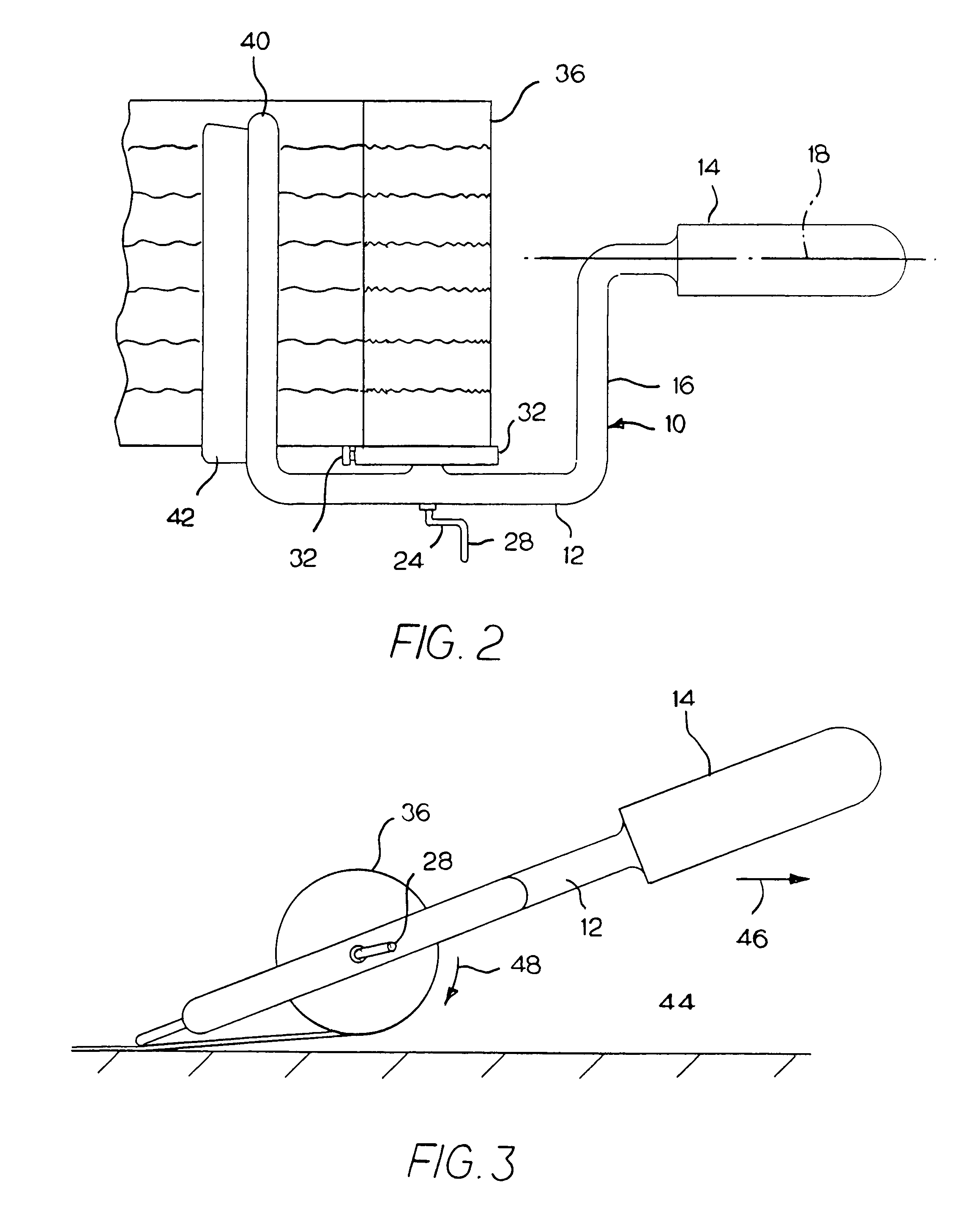
[0017]Referring to the drawings, a preferred border guide 10 comprises a body 12 preferably having an integral handle 14. For illustrative purposes, the length of handle 14 is about 5½″. The body includes an arm 16 which is at right angles to the axis 18 of the handle, and a second arm supported along an axis 22 that is parallel to arm 16 and also at right angles to the axis 18 of the handle and lying in the same plane as axis 18. Arm 20 is about 2½″ from arm 16.

[0018]A crank 24 is mounted on the body and attached to a shaft 26 which extends through the longitudinal center of arm 20. The shaft is rotatable in the arm by rotating crank handle 28.

[0019]A sleeve 30 (roller) is slidably mounted on arm 20 and has a length greater than arm 16. The outer end of shaft 26 is frictionally connected to sleeve 30 so that by rotating the crank handle, the sleeve is rotated. A disc-like seat 32 is mounted on arm 20. A threaded fastener 34, mounted on the seat, engages arm 20, to lock the seat in ...


PUM

PropertyMeasurementUnit
Lengthaaaaaaaaaa
Adhesivityaaaaaaaaaa
Widthaaaaaaaaaa

Abstract

A border guide and method for applying an elongated strip of border paper in a horizontal position on a vertical wall. The paper is soaked in water to activate the adhesive and then wound on a roll on the border guide. The user then presses one end of the border guide to the wall and unrolls the roll of paper as he removes the handle in a horizontal position. A squeegee presses the paper to the wall as it is being unwound.

Description

BACKGROUND OF THE INVENTION[0001]This invention is related to a method and a device for attaching a paper border on a vertical wall. One of the problems with attaching a paper border on a wall is that normally the entire length of paper is soaked in water to activate the adhesive. The paper border which may be several feet long must then be held by one person so that the different sections of the paper do not contact one another while the adhesive is wet. A second person then progressively presses the paper border to the wall in a horizontal motion. This is a time-consuming process and may take an hour or so to apply a single strip of paper.[0002]This problem has been addressed in the prior art. See for example U.S. Pat. No. 5,328,543, issued Jul. 12, 1994, to Thomas G. Campagna for “Border Guide”. This patent discloses a housing mounted on the upper end of a long pole. The pole supports the paper and the housing at a height that generally corresponds to the height to which the pape...

Claims


Application Information

Patent Timeline
IPC IPC(8): B32B37/00B32B39/00B44C7/06
CPCB44C7/06Y10T156/1793Y10T156/1352Y10T156/1788Y10T156/1348Y10T156/18
Inventor BREWER, ROBERT F.BUNCH, AARON T
Owner BREWER ROBERT F
Why Eureka
Try Eureka