Snowmobile rider positioning
a technology for snowmobiles and riders, applied in the direction of sledges, bicycle equipment, vehicles, etc., can solve the problems of prohibitively large jostling forces, and achieve the effect of reducing the effect of snowmobile movemen
- Summary
- Abstract
- Description
- Claims
- Application Information
AI Technical Summary
Benefits of technology
Problems solved by technology
Method used
Image
Examples
first embodiment
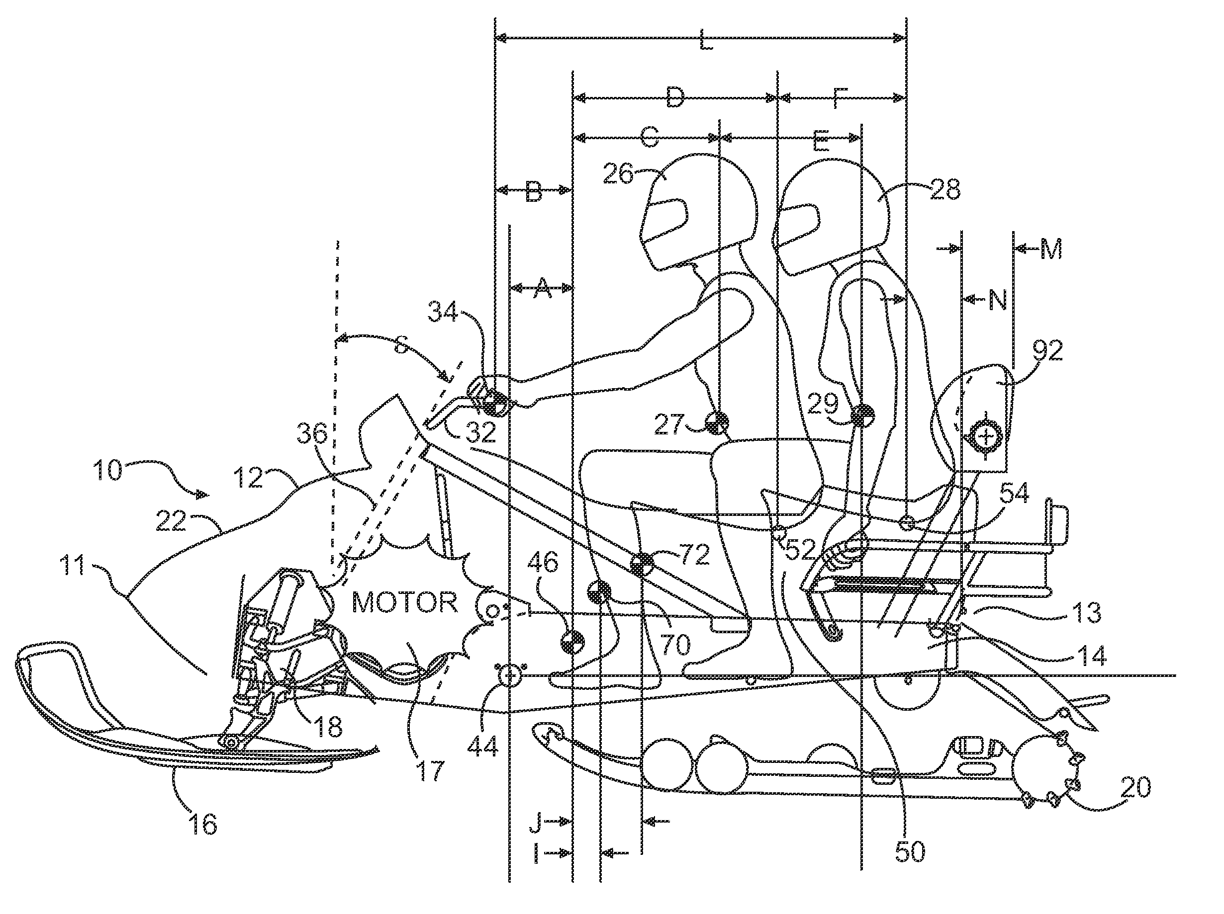
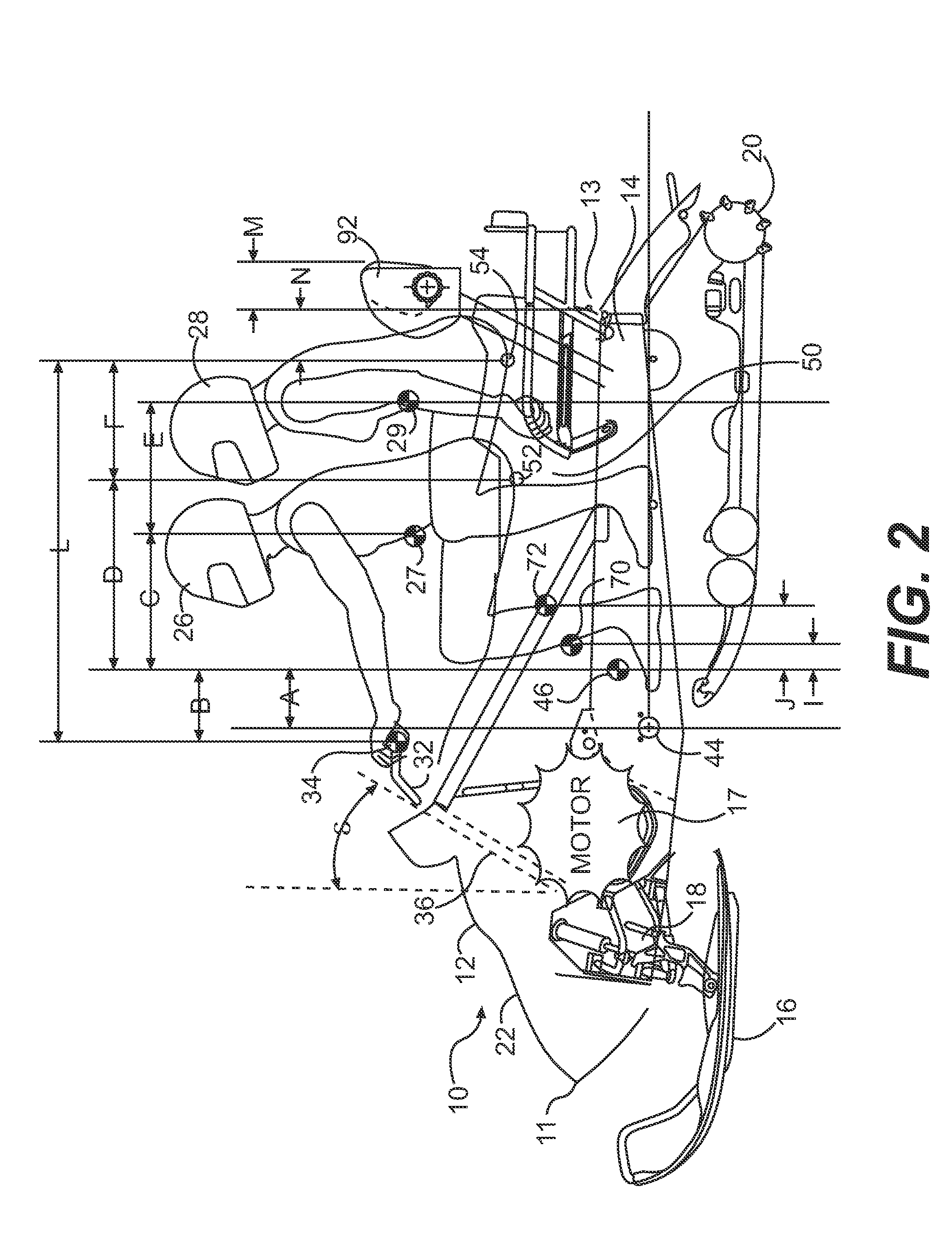
[0039]FIG. 2 illustrates the snowmobile 10. The snowmobile 10 has a forward end 11 and a rearward end 13 that are defined consistently with the travel direction of the snowmobile 10. The snowmobile 10 includes a body 12 (i.e., the exterior upper portions) and a frame 14. A motor 17, such as an internal combustion engine, is carried by the frame 14 at the forward end 11. In addition, two skis 16 are attached to the forward end 11 of the frame 14 through a suspension system 18. It should be noted, however, that a single centered ski would also work with the invention. A drive track 20 is disposed under frame 14 and is connected operatively to the engine 17 for propulsion of the snowmobile 10.
[0040]At the front 11 of the frame 14, the snowmobile 10 includes fairings 22 that enclose the engine 17 to protect it and to provide an external shell that can be decorated so that the snowmobile 10 is aesthetically pleasing. Typically, the fairings 22 comprise a hood and a bottom pad (neither of...
fourth embodiment
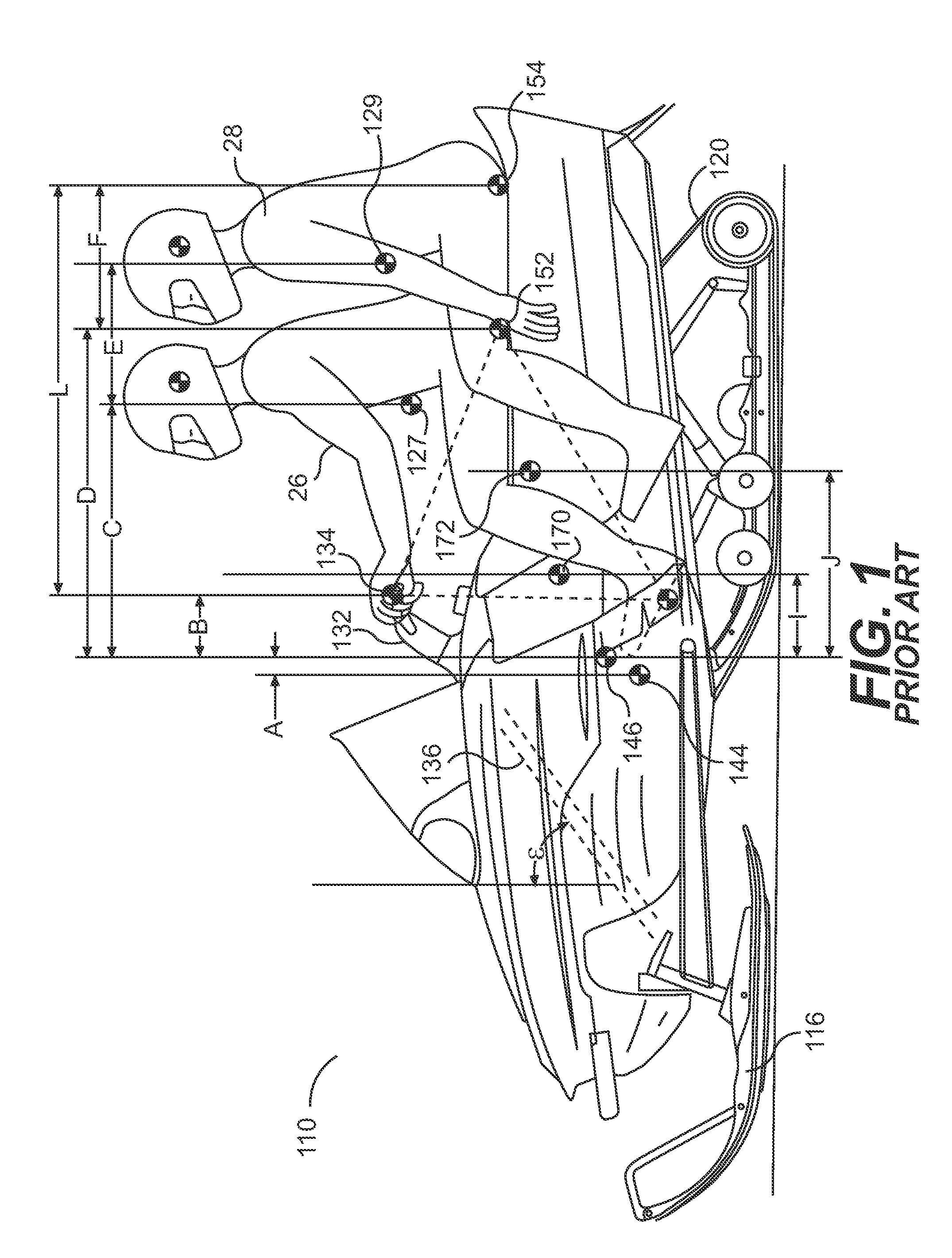
[0088]FIG. 8 illustrates the relevant spatial relationships for the fourth embodiment and shows that the centers of gravity of the riders 26, 28, 30 are disposed closer to the center of gravity 446 of the snowmobile than in conventional snowmobiles 110.
[0089]The center of gravity 427 of the first rider 26 on the snowmobile 410 is preferably between 220 mm and 270 mm behind the center of gravity 446 of the snowmobile 410, more preferably between 230 mm and 260 mm behind the center of gravity 446, even more preferably between 240 mm and 250 mm behind the center of gravity 446, and most preferably about 245 mm behind the center of gravity 446.
[0090]The center of gravity 429 of a second rider 28 on the snowmobile 410 is disposed behind the center of gravity 446 of the snowmobile 410 by a distance calculated as distance C plus distance E. This distance is preferably between 590 mm and 640 mm, more preferably between 600 mm and 630 mm, even more preferably between 610 mm and 620 mm, and m...
third embodiment
[0099]As in the third embodiment, a support element 560 extends upwardly and rearwardly from the back end 514″ of the frame 514 to provide support for the second seat section 550″. The third seat position 556 and back end of the third seat position 556 extend behind the back end 514″ of the frame 514 by distances N and M, respectively. Distance N is always positive and preferably between 35 mm and 85 mm. Distance N is more preferably between 45 mm and 75 mm. Distance N is even more preferably between 55 mm and 65 mm. Distance N is most preferably about 60 mm. Distance M is always positive and preferably between 265 mm and 315 mm. Distance M is more preferably between 275 mm and 305 mm. Distance M is even more preferably between 285 mm and 295 mm. Distance M is most preferably about 290 mm.
[0100]A center of gravity 570 of the combined weight of the snowmobile 410 and rider 26 is disposed behind the center of gravity 546 of the snowmobile 510 without a rider. A center of gravity 572 o...
PUM
 Abstract
Description
Claims
Application Information
 - R&D
- Intellectual Property
- Life Sciences
- Materials
- Tech Scout
- Unparalleled Data Quality
- Higher Quality Content
- 60% Fewer Hallucinations
Browse by: Latest US Patents, China's latest patents, Technical Efficacy Thesaurus, Application Domain, Technology Topic, Popular Technical Reports.
© 2025 PatSnap. All rights reserved.Legal|Privacy policy|Modern Slavery Act Transparency Statement|Sitemap|About US| Contact US: help@patsnap.com


