Vehicle front-part structure

a front-part structure and vehicle technology, applied in the direction of roofs, vehicle arrangements, transportation and packaging, etc., can solve the problems that the impact absorbing members of the right and left hand side and the impact absorbing members cannot absorb the impact energy at all

Active Publication Date: 2007-05-08
MAZDA MOTOR CORP
View PDF26 Cites 73 Cited by
  • Summary
  • Abstract
  • Description
  • Claims
  • Application Information

AI Technical Summary

Benefits of technology

[0008]In view of the above described problems, it is an object of the present invention to provide an automobile front-part structure in which an impact absorbing member can absorb the impact energy that is given by a bump, whatever bump it is, such as an offset collision and a pole bump.

Problems solved by technology

But, in the case of a right-and-left offset collision between two vehicles(i.e., an offset collision), both right and left impact absorbing members cannot absorb the impact energy.
Besides, if a vehicle hits on a narrow object such as a pole (i.e., a pole bump),.then depending upon the bump position, the impact absorbing members could not absorb the impact energy at all.

Method used


Image

  • Vehicle front-part structure
  • Vehicle front-part structure
  • Vehicle front-part structure

Examples


Embodiment Construction

[0020]Hereinafter, the automobile front-part structure according to each embodiment of the present invention will be described with reference to the drawings. Herein, the frames and the members according to each embodiment are made of steel, unless they are specifically mentioned otherwise.

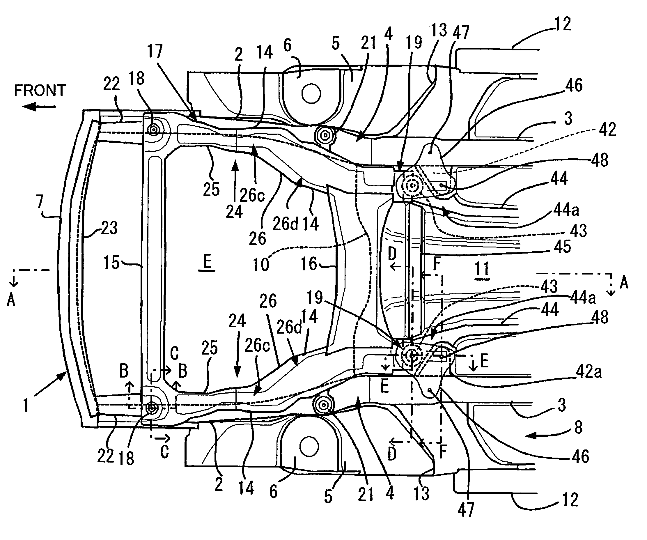
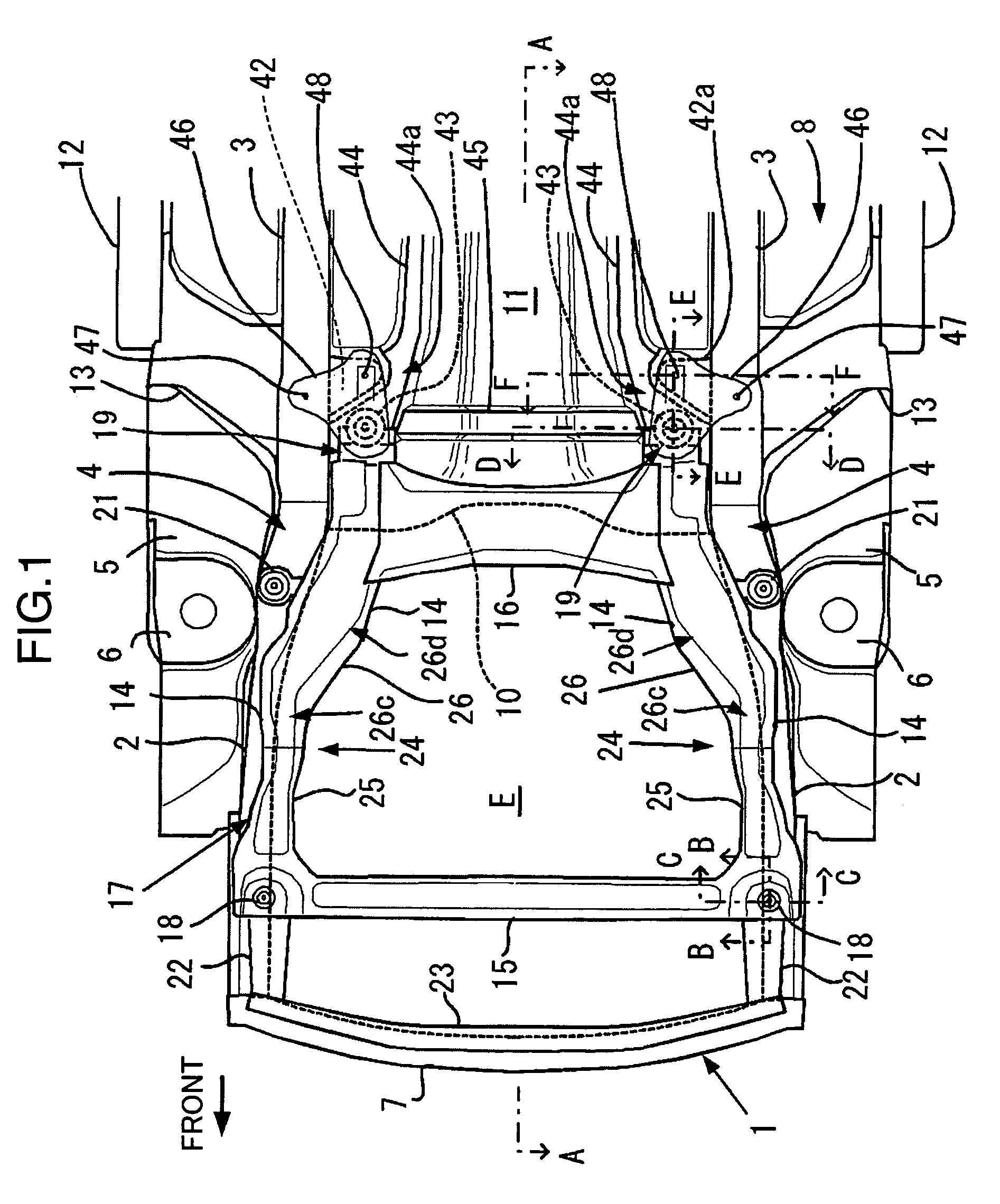
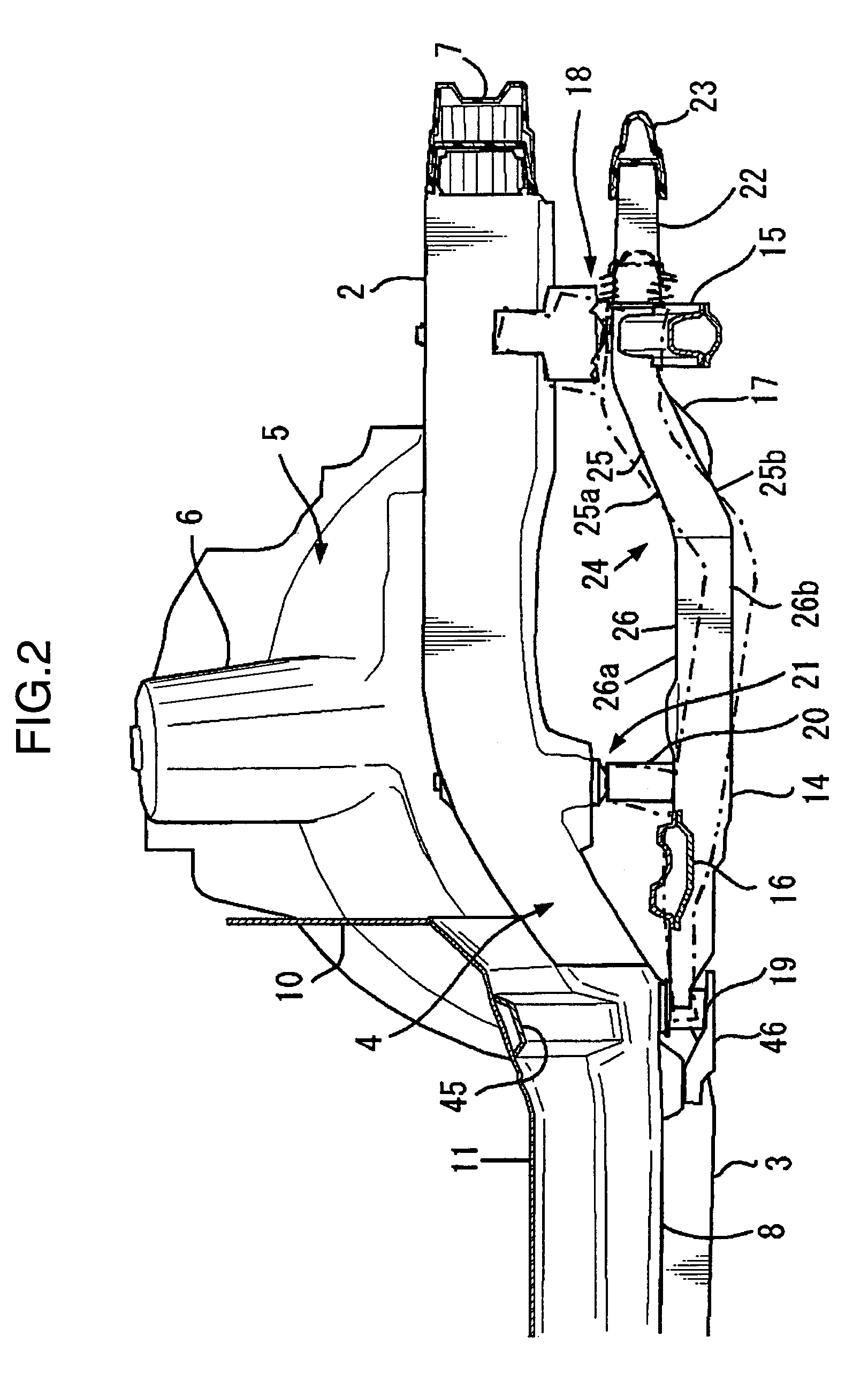
[0021]FIG. 1 is a plan view, seen from the bottom surface of a vehicle, of a front sub-frame, a vehicle-body frame, and the like, according to an embodiment of the present invention. FIG. 2 is a sectional view, seen along an A—A line of FIG. 1. FIG. 3 is a perspective view of only the front sub-frame, seen obliquely from forward. FIG. 4 is a sectional view, seen along a B—B line of FIG. 1. FIG. 5 is a sectional view, seen along a C—C line of FIG. 1. FIG. 6 is a sectional view, seen along a D—D line of FIG. 1. FIG. 7 is a sectional view, seen along an E—E line of FIG. 1. FIG. 8 is a sectional view, seen along an F—F line of FIG. 1.

[0022]As shown in FIG. 1 and FIG. 2, a vehicle-body frame 1 includes...


PUM


Abstract

An automobile front-part structure is provided in which an impact-absorbing member can absorb the impact energy that is given by a bump, whatever bump it is, such as an offset collision and a pole bump. This automobile front-part structure including: a pair of vehicle-body frames which extends in the front-and-rear directions along both sides of a vehicle, and whose front-end parts extend up to the front part of an automobile; and a front sub-frame which is supported with the vehicle-body frames in the front part of the vehicle, and is disposed below the vehicle-body frames, in which the front sub-frame includes: a front sub-frame main-body which has, a pair of right and left side frames which extends in the front-and-rear directions of the vehicle, and a cross member which is formed by a reinforcement and bridges the front parts of the side frames; a pair of right and left impact absorbing members which is formed by a crush pipe, is disposed at the front-end parts of the side frames in the front sub-frame main-body and absorbs impact energy from ahead; and a reinforcement which bridges the front ends of both impact absorbing members.

Description

BACKGROUND OF THE INVENTION[0001]1. Field of the Invention[0002]The present invention relates to an automobile front-part structure which includes side frames that are provided below vehicle-body frames of an automobile and extend in the vehicle front-and-rear directions. Particularly, it relates to an art where impact-absorbing members are provided at the vehicle-front parts of the side frames.[0003]2. Description of the Related Art[0004]Conventionally, for example, as disclosed in Japanese Utility Model Laid-Open No. 3-91282 (Japanese Utility Model Registration No. 2514565) specification, it is publicly known that below a vehicle-body frame (for example, which corresponds to a front cross-member 12 according to this specification) of an automobile (i.e., a vehicle), there is provided a front sub-frame which is formed by a pair of right and left side frames which each extend close to the front-end part of the vehicle-body frame along the vehicle front-and-rear directions.[0005]In a...

Claims


Application Information

Patent Timeline
Patent Type & Authority Patents(United States)
IPC IPC(8): B60J7/00B62D21/11B62D21/15
CPCB62D21/11
Inventor MURATA, SHINKONUMA, SHINICHIHANAZAKI, MASANOBU
Owner MAZDA MOTOR CORP
Why Eureka
Try Eureka