
Flexible perimeter lighting apparatus

a flexible, perimeter lighting technology, applied in the direction of lighting support devices, identification means, instruments, etc., can solve the problems of bulb failure, relative short life, and large consumption of power

Active Publication Date: 2007-05-08
THE SLOAN COMPANY INC DBA SLOANLED
View PDF20 Cites 113 Cited by
  • Summary
  • Abstract
  • Description
  • Claims
  • Application Information

AI Technical Summary

Problems solved by technology

Some of the disadvantages of these bulbs are that they have a relatively short life, are fragile and can consume a relatively large amount of power.
Also, neon bulbs can experience difficulty with cold starting, which can lead to the bulb's failure.
One disadvantage of this strip is that it cannot be cut to different lengths for different applications.
This arrangement is not durable enough to withstand the conditions for outdoor use.
The flexible tape and its adhesive can easily deteriorate when continually exposed to the elements.
This arrangement is also not durable enough to withstand the conditions for outdoor use.
One of the disadvantages of this strip lighting is that it is not suitable for replacing neon type perimeter lighting because the light from the individual light bulbs is not diffused and dispersed to give the appearance of a neon light source.
Furthermore, no mechanism is disclosed for mounting the strip lighting to a structure.
Another disadvantage is that the strip lighting uses light bulbs instead of LEDs, and light bulbs generally have a shorter life span and can consume more power than LEDs.
One of the disadvantages of this light is that it is not flexible and that it cannot be cut to match the length of a building's structural features.
Also, the connectors between adjacent sections of lighting are bulky and result in a visible junction between the sections.
The light's tube also significantly attenuates the light emitted by its LEDs, significantly reducing the light's brightness.
There is also no apparatus or method for providing perimeter lighting that can be bent to match a curved structural feature of a building.

Method used


Image

  • Flexible perimeter lighting apparatus
  • Flexible perimeter lighting apparatus
  • Flexible perimeter lighting apparatus

Examples


Embodiment Construction

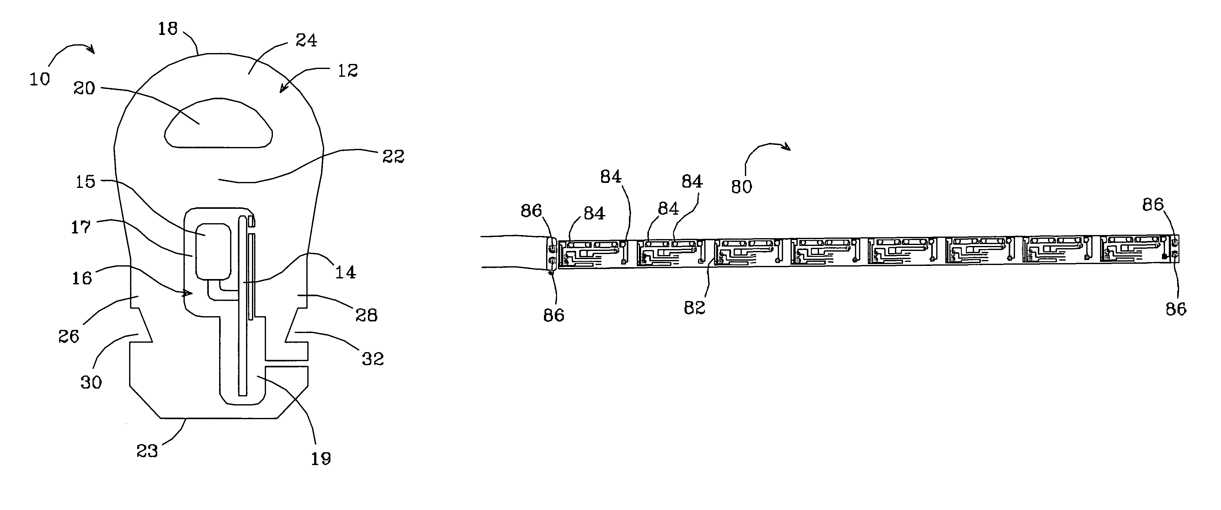
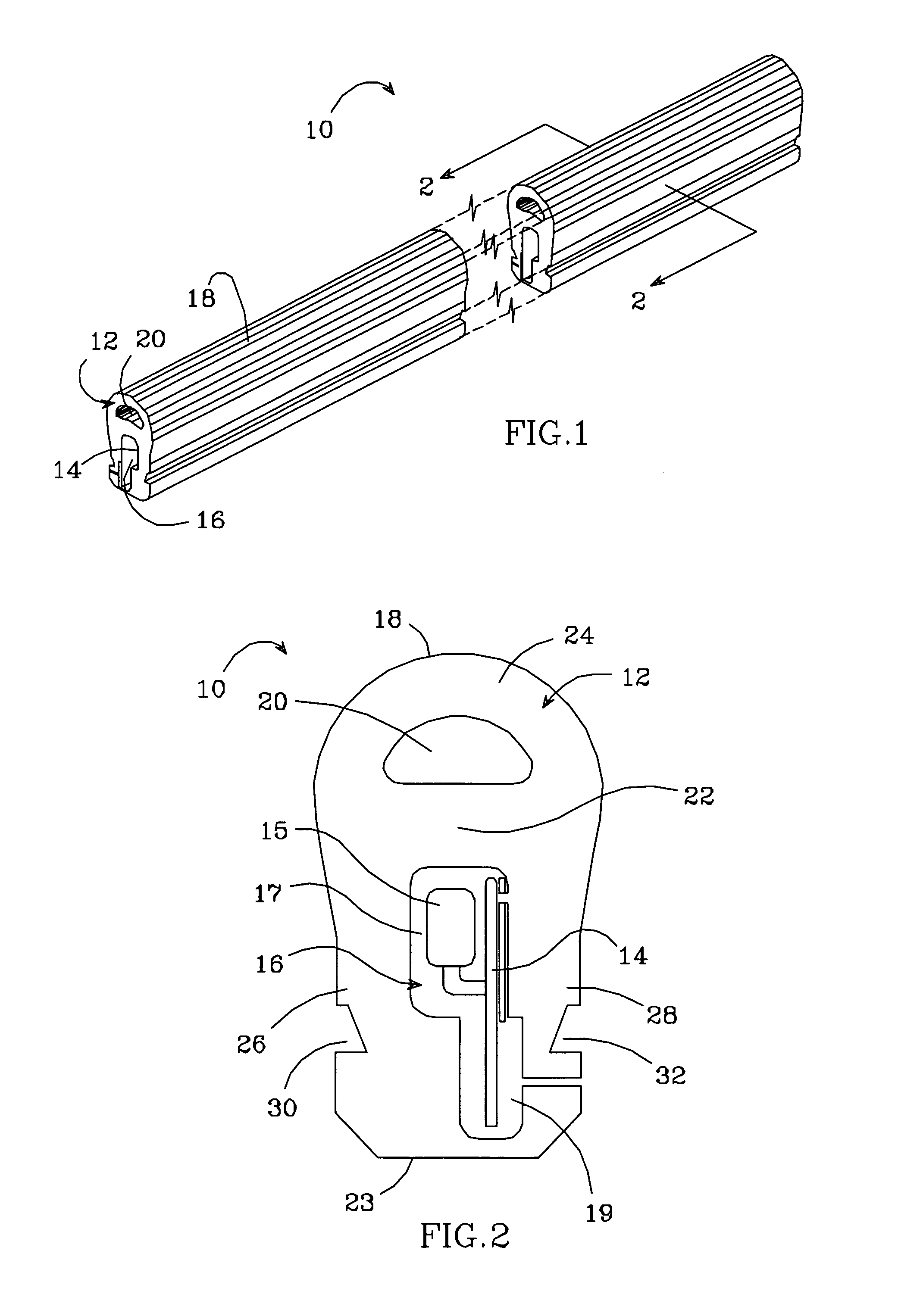
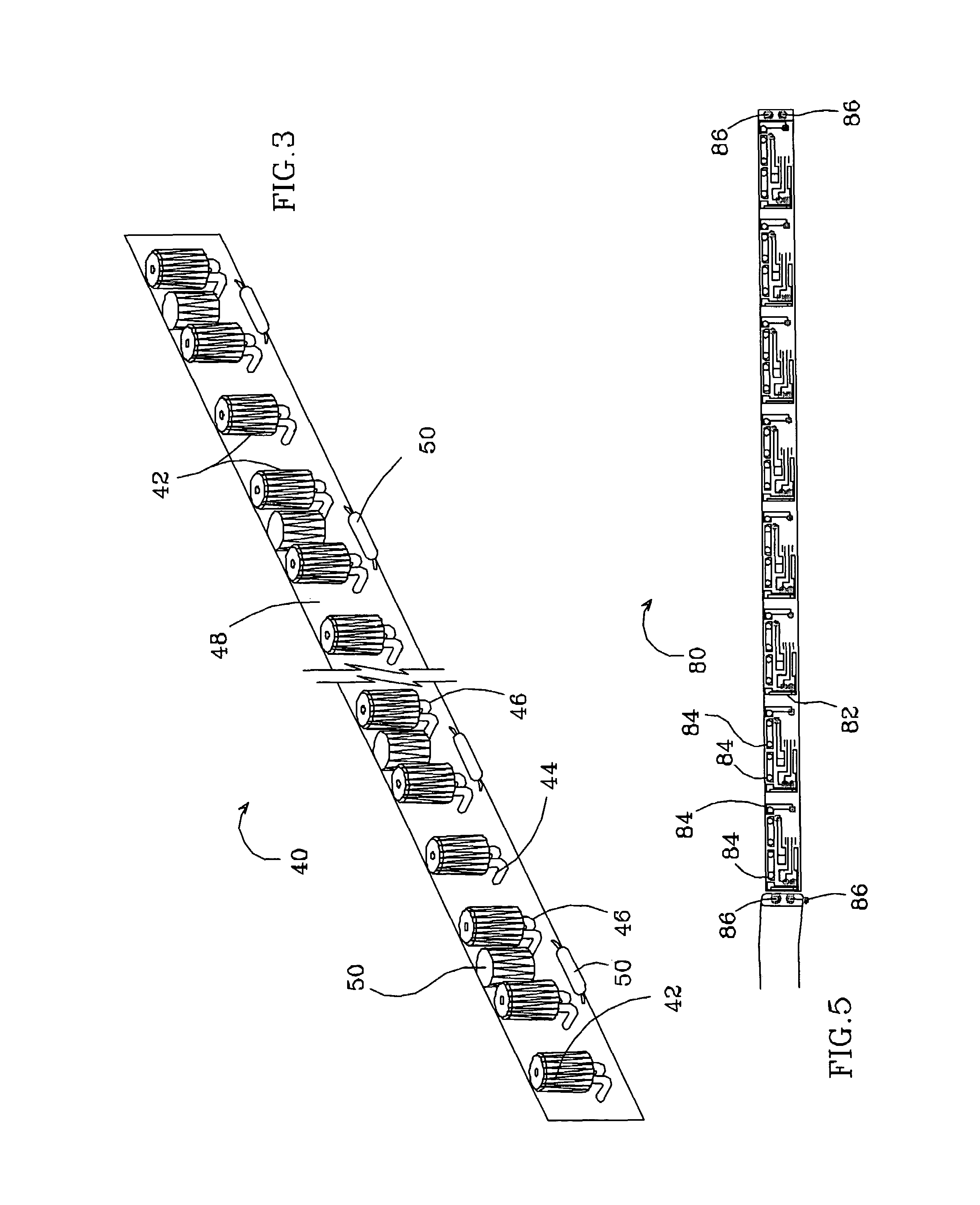
[0047]FIGS. 1 and 2 show one embodiment of a flexible lighting system 10 according to the present invention that generally comprises an elongated flexible extrusion 12 and an elongated flexible printed circuit assembly 14. The extrusion 12 can be many shapes and sizes, but is preferably sized to replace conventional neon lighting. Some standard sizes for neon lighting include, but are not limited to, 12 millimeter (mm), 15 mm, and 18 mm, and the extrusion can be sized accordingly to appear as these lights. The lighting system should also have optical properties designed to match and replace industry standard neon lights. The lighting systems according to the present invention can use light sources (such as LEDs) that are more efficient and have a longer life than conventional neon lights. The resulting lighting system can cost less over its lifetime, consume less power, and require less maintenance, compared to conventional neon lighting.

[0048]The printed circuit assembly 14 is moun...


PUM


Abstract

An elongated flexible lighting system according to the present invention includes an array of light sources that are illuminated by electric power. It further includes an elongated translucent extrusion of flexible material. The array of light sources is integral to the extrusion with said extrusion transmitting and dispersing the light from the array such that the lighting system gives the appearance that the array of light sources is a continuous light source. The elongated lighting system can be used for many different applications including, but not limited to, the lighting of structural features and illumination of sign features.

Description

BACKGROUND OF THE INVENTION[0001]1. Field of the Invention[0002]This invention relates to an elongated lighting system and more particularly to an elongated and flexible lighting system using light emitting diodes as its light source.[0003]2. Description of the Related Art[0004]Perimeter or border lights (“perimeter lighting”) are commonly used on buildings to accentuate the structure, to draw customer attention to the building, and to provide safety lighting. Lighted signs are also commonly used with business to advertise products or to indicate whether the business is open or closed. Most conventional perimeter lighting systems and lighted signs use neon or fluorescent bulbs as the light source. Some of the disadvantages of these bulbs are that they have a relatively short life, are fragile and can consume a relatively large amount of power. Also, neon bulbs can experience difficulty with cold starting, which can lead to the bulb's failure.[0005]Developments in light emitting diod...

Claims


Application Information

Patent Timeline
Patent Type & Authority Patents(United States)
IPC IPC(8): F21V5/08F21S4/00F21V21/005F21V21/088F21V23/06G09F9/33
CPCF21S4/003F21V21/005F21V21/088F21V23/06G09F9/33F21Y2101/02G09F2013/1895F21S4/20F21Y2115/10
Inventor SLOAN, THOMAS C.QUAAL, BRUCE
Owner THE SLOAN COMPANY INC DBA SLOANLED
Learn More