Micromirror devices with in-plane deformable hinge

a technology of hinges and micromirrors, applied in the field of microelectromechanical devices, can solve the problems of low light efficiency of devices and lowering the contrast ratio (modulation depth) of displays

Active Publication Date: 2007-05-08
VENTURE LENDING & LEASING IV +1
View PDF18 Cites 55 Cited by
  • Summary
  • Abstract
  • Description
  • Claims
  • Application Information

AI Technical Summary

Problems solved by technology

Although the switching voltage of this SLM is lowered by connecting the deflectable mirror elements at only one corner, the device has low light efficiency due to the small fractional active area.
In addition, diffraction from the addressing circuitry lowers the contrast ratio (modulation depth) of the display.

Method used


Image

  • Micromirror devices with in-plane deformable hinge
  • Micromirror devices with in-plane deformable hinge
  • Micromirror devices with in-plane deformable hinge

Examples


Embodiment Construction

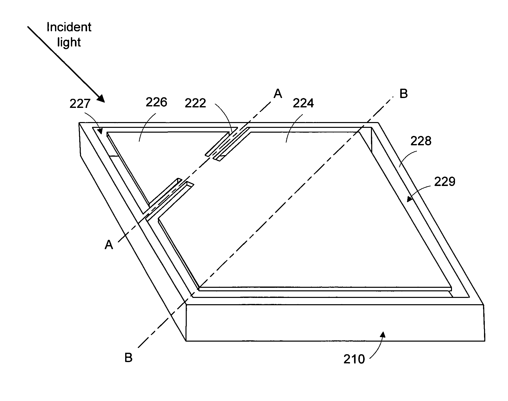
[0024]The micromirror device of the present invention comprises a deflectable and reflective mirror plate that is connected to a deformable hinge located in the same plane as the mirror plate. The mirror plate is operable to rotate at a rotation axis that is parallel to but offset from a diagonal of the mirror plate or, is parallel to but offset from an in-plane symmetric axis of the mirror plate. In either configuration, the rotation axis, as well as the deformable hinge may or may not be disposed at an edge of the deflectable and reflective mirror plate.

[0025]The deformable hinge is held by a frame having a frame wall. The frame, hinge, and mirror plate is preferably, but not required, fabricated from the same substrate, such as a single crystal. The mirror plate may have a reflective surface coated with a material for efficiently reflecting visible light, particularly, a metallic material with high reflectivity to visible light.

[0026]For deflecting the mirror plate with, for exam...


PUM


Abstract

Disclosed herein is a micromirror device having in-plane deformable hinge to which a deflectable and reflective mirror plate is attached. The mirror plate rotates to different angles in response to an electrostatic field established between the mirror plate and an addressing electrode associated with the mirror plate.

Description

CROSS-REFERENCE TO RELATED PATENT APPLICATIONS[0001]This patent application is a continuation-in-part of U.S. patent application Ser. No. 10 / 927,560 filed Aug. 25, 2004, now U.S. Pat. No. 6,980,349 the subject matter being incorporated herein by reference.TECHNICAL FIELD OF THE INVENTION[0002]The present invention is related generally to art of microelectromechanical devices, and, more particularly, to micromirror devices.BACKGROUND OF THE INVENTION[0003]Spatial light modulators (SLMs) are transducers that modulate an incident beam of light in a spatial pattern in response to an optical or electrical input. The incident light beam may be modulated in phase, intensity, polarization, or direction. This modulation may be accomplished through the use of a variety of materials exhibiting magneto-optic, electro-optic, or elastic properties. SLMs have many applications, including optical information processing, display systems, and electrostatic printing.[0004]A SLM in which movable elemen...

Claims


Application Information

Patent Timeline
Patent Type & Authority Patents(United States)
IPC IPC(8): G02B26/00G02B26/08
CPCG02B26/0841Y10S359/904G02B27/1033
Inventor HUIBERS, ANDREWPATEL, SATYADEVDOAN, JONATHANDUNPHY, JAMESSIMONIAN, DMITRISHI, HONGQINZHANG, JIANGLONG
Owner VENTURE LENDING & LEASING IV
Why Eureka
Try Eureka