Geometric correction of rough wireframe models derived from photographs

a wireframe model and geometric correction technology, applied in the field of computer modeling of physical objects, can solve the problems of poor ability to correctly determine the pitch of sloped roof facets, poor determination of layered or underhanging roof sections, and “lean” roofs within images, etc., and achieve the effect of speed sacrifi

Active Publication Date: 2011-08-04
EAGLEVIEW TECH
View PDF100 Cites 131 Cited by
  • Summary
  • Abstract
  • Description
  • Claims
  • Application Information

AI Technical Summary

Benefits of technology

[0020]The third method also sacrifices speed and requires more user skill than the first method, but the resulting model is a very accurate reflection of the correct geometric form of the house in the photograph and does not depend on previous knowledge of the roof facet pitches.

Problems solved by technology

One disadvantage is that incorrect line lengths on sloped roof facets will result when the image is not taken from directly overhead, resulting in a “lean” of the roof within the image.
Another disadvantage is that there is a poor ability to correctly determine pitches on sloped roof facets.
Other problems are a poor determination of layered or underhanging roof sections.
While this method has the advantage that a skilled operator can produce geometrically correct models, it has the disadvantage that it is harder to create from an image and it becomes more time consuming with increasing roof complexity.
In addition, complex user interface software is required, which requires greater training.
Unfortunately, the detailed 3D model made this way cannot be easily imported to some widely used home construction CAD software programs.
The disadvantages of this third method are that greater training is required as compared to the first method and it becomes harder and more time consuming with increasing roof complexity without further processing or touch-up of the model to meet import requirements of the 3rd party software.

Method used


Image

  • Geometric correction of rough wireframe models derived from photographs
  • Geometric correction of rough wireframe models derived from photographs
  • Geometric correction of rough wireframe models derived from photographs

Examples


Embodiment Construction

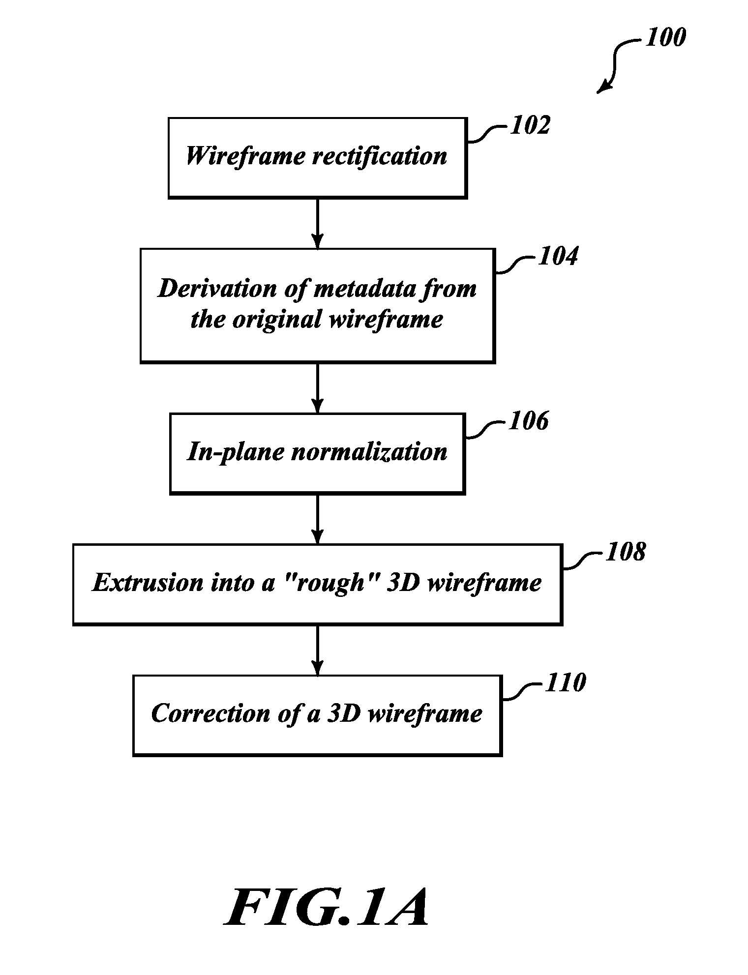
[0040]FIG. 1A is a flow chart showing an example process 100 of geometric correction of rough wireframe models derived from photographs, according to one embodiment. In particular, FIG. 1A illustrates process 100 that may be performed or implemented by, for example, one or more software modules or components or any combination of suitable hardware, firmware or software components or devices including those that are a part of or configure the computing environment of FIG. 7.

[0041]While each of the steps shown in FIG. 1A contributes to the overall solution, each can be used independently or in various combinations to yield improvements in obtaining a 2D or 3D wire model as discussed below. Below is an overview of each step in the process, which will be followed by a more detailed discussion of each step.

[0042]At 102, the process performs wireframe rectification. This is a pre-cursor step that can optionally be used within or as a precursor to each of the other four steps that follow. ...


PUM


Abstract

Geometric correction of rough wireframe models derived from photographs may include rectification of either a 2D or 3D original wireframe model of a roof structure, derivation of metadata from the original wireframe, in-plane normalization of the wireframe, extrusion into a “rough” 3D wireframe based on the normalized wireframe, and correction of the “rough” 3D wireframe. The correction and normalization may be an iterative process based on initial pitch values, metadata derived from the original or corrected wireframe models and defined constraints regarding relationships between roof portions or segments. The iterative process may repeat adjusting the wireframe model until the adjusting converges to a stable state according to the various defined constraints.

Description

BACKGROUND[0001]1. Technical Field[0002]This invention is in the field of computer modeling of physical objects and, in particular, the generation of a three-dimensional model using one or more two-dimensional photographs as a starting data set.[0003]2. Description of the Related Art[0004]Several methods can be employed to generate a three-dimensional computer model of a roof in the form of a wire-frame using one or more overhead photographs.[0005]A first method is to trace the image in the photograph with or without user input. Using this tracing method on a photograph that provides a nearly top-down view of the structure of interest, a computer-aided design (CAD) tool allows lines and polygons to be drawn over the background image. The resulting wireframe model reflects the lines and contours of interest in the locations they are observed in the photograph.[0006]While this method has the advantage that it is fast and compatible with many off-the-shelf CAD and drawing tools that do...

Claims


Application Information

Patent Timeline
Patent Type & Authority Applications(United States)
IPC IPC(8): G06T17/00
CPCG06T17/20G06T2210/04G06T19/20
Inventor PERSHING, CHRISKEANE, JOHN F.
Owner EAGLEVIEW TECH
Why Eureka
Try Eureka