Grating trim retarders

a technology of grating and retarders, applied in optics, color television details, instruments, etc., can solve the problems of unsuitable projection contrast compensation devices, devices that are too reflective to be used as trim retarders, and devices that are particularly unsuitable for projection contrast compensation, etc., to achieve the effect of improving image contrast in polarization-based

Inactive Publication Date: 2007-03-29
VIAVI SOLUTIONS INC
View PDF21 Cites 126 Cited by
  • Summary
  • Abstract
  • Description
  • Claims
  • Application Information

AI Technical Summary

Benefits of technology

[0036] The instant invention relates to optical retarders that include both transversely- and axially-inhomogeneous structures. In particular, the instant invention relates to trim retarders that include an A-plate grating, which has a periodic section along the transverse plane of the device, and a −C-plate grating, which has a periodic section along the device normal. The widths of the periodic walls in the A-plate grating, and the thicknesses of the periodic layers in the −C-plate grating, are selected to be a fraction of the operating wavelengths in order to provide form-birefringence effects. These zeroth order gratings are readily coupled with one or more AR coatings to provide a low-reflectance, full-function trim retarder that is valuable for improving image contrast in polarization-based micro-display imagers.
[0037] The instant invention further relates to polarization-based projection display systems (e.g., with reflective liquid-crystal-on-silicon (LCoS) or transmissive liquid crystal display (xLCD) panels) that include the full-function trim retarder (i.e., with both transversely- and axially-inhomogeneous structures). In these projection systems, the full-function trim retarder is typically included as a separate element or is integrated with another optical element. For example, with regard to the latter, the full-function trim retarder is easily integrated into one or both substrates sandwiching the liquid crystal display cell.

Problems solved by technology

Note that although the two materials / regions provide different phase delays in theory, in practice, an averaging effect results due to the fact that the light is unable to resolve the sub-wavelength pitch.
While this wire-grid device is suitable for visible band applications, the polarizing (diattenutation) characteristics of the wire grid are high, and as a result, this device is too reflective to be used as a trim retarder.
However, since the proposed device requires a high-angle conical mount and it is meant for parallel beam applications, it is not suitable for conventional LCD-based micro-display imager applications.
Furthermore, a lack of −C-plate functionality renders the device particularly unsuitable for projection contrast compensation.
While the optical retarder taught by Deng et al. has been used in a variety of optical applications, including polarizers, isolators, and AR design, it not generally suitable for LCD-based micro-display imager applications, and in particular projection applications, due to the lack of a −C-plate component and a high crossed polarization reflectance, the latter of which is due to the use of high effective in-plane birefringence.
Unfortunately, this approach greatly restricts the type of dielectric form birefringent compensator material for use therein, and requires accurate measurement of material constants and coating thicknesses.

Method used


Image

  • Grating trim retarders
  • Grating trim retarders
  • Grating trim retarders

Examples


Embodiment Construction

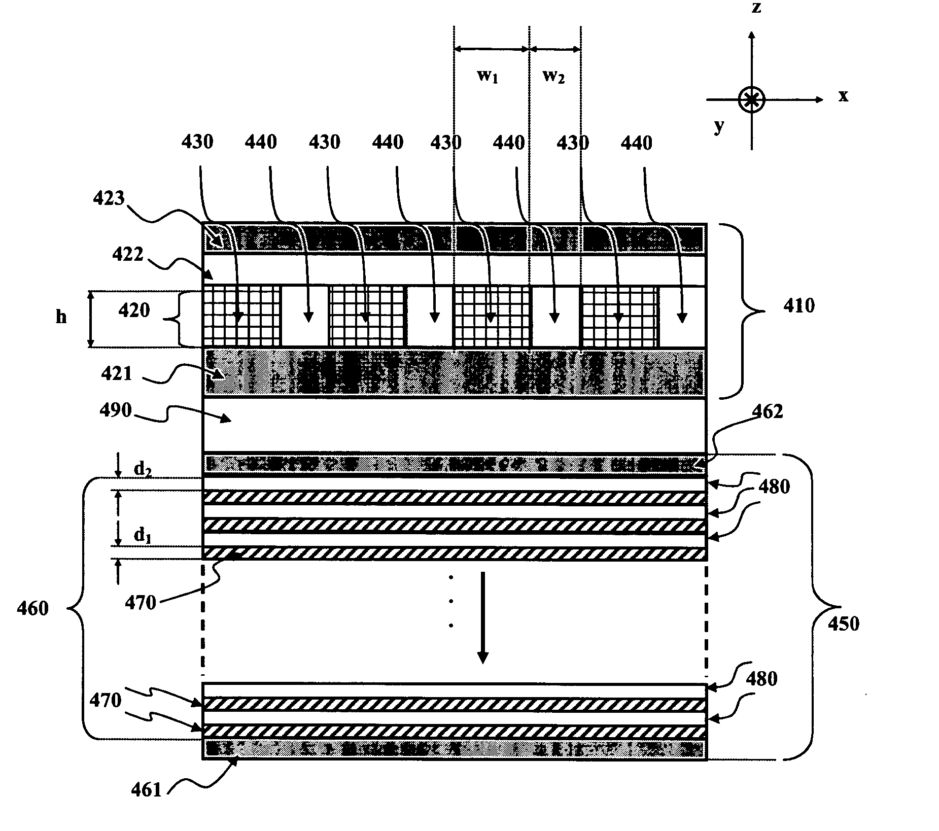
[0136] Referring to FIG. 11, there is shown a full function A / −C-plate grating trim retarder in accordance with one embodiment of the instant invention. The full function A / −C-plate grating trim retarder 400 includes a transversely-inhomogeneous A-plate grating element 410 and an axially-inhomogeneous −C-plate grating element 450, each coupled (incoherently) to opposite surfaces of a transparent substrate 490. More specifically the transversely-inhomogeneous A-plate grating element 410, which is a grating anti-reflection (AR) element, is mounted on a first surface of a transparent substrate 490, while the axially-inhomogeneous −C-plate grating element 450, which is a form-birefringence anti-reflection (FBAR) element, is mounted on a second surface of the transparent substrate 490.

[0137] The A-plate grating AR element 410 includes a transverse grating 420, an optional etch-stop stack 421 (e.g., including one or more etch-stop layers), an optional cap-stack 422 (e.g., including one o...


PUM

PropertyMeasurementUnit
wavelength rangeaaaaaaaaaa

Abstract

A grating trim retarder fabricated from a form-birefringent multi-layer dielectric stack including at least one anti-reflection coating and supported on a transparent substrate is provided. The form-birefringent dielectric stack includes an axially-inhomogeneous element in the form of a −C-plate grating and a transversely-inhomogeneous element in the form of an A-plate grating. Each of the −C-plate and the A-plate gratings are fabricated with dimensions to form a zeroth order sub-wavelength grating structure. Fabricating the grating trim retarder with anti-reflection coatings and / or a segment where the −C-plate and A-plate grating overlap enables the in-plane and out-of-plane retardances to be tailored independently according to the desired application.

Description

CROSS-REFERENCE TO RELATED APPLICATIONS [0001] This application is a continuation-in-part of U.S. application Ser. No. 11 / 009,476 filed on Dec. 10, 2004 and which claims priority from U.S. patent applications Ser. Nos. 60 / 529,315 filed Dec. 11, 2003; 60 / 587,924 filed Jul. 14, 2004; 60 / 589,167 filed Jul. 19, 2004, and 60 / 586,542 filed Jul. 9, 2004, all of which are hereby incorporated by reference. This application claims priority from U.S. Provisional Application Nos. 60 / 734,072 filed Nov. 7, 2005, 60 / 821,313 filed Aug. 3, 2006, all of which are hereby incorporated by reference.MICROFICHE APPENDIX [0002] Not Applicable. TECHNICAL FIELD [0003] The present application relates generally to optical retarders, and in particular, to grating trim retarders and / or liquid crystal display based micro-display projection systems including the same. BACKGROUND OF THE INVENTION [0004] Liquid-crystal displays (LCDs) are widely used in projection displays for large screen televisions and monitors. ...

Claims


Application Information

Patent Timeline
Patent Type & Authority Applications(United States)
IPC IPC(8): G02F1/1335
CPCG02B5/3058G02B5/3083H04N9/3197H04N9/3167G02F1/133634
Inventor TAN, KIM L.HENDRIX, KAREN D.HULSE, CHARLES A.HRUSKA, CURTIS R.
Owner VIAVI SOLUTIONS INC
Why Eureka
Try Eureka