Eureka AIR delivers breakthrough ideas for toughest innovation challenges, trusted by R&D personnel around the world.

Envelope for optical fibres

Inactive Publication Date: 2007-05-08
TYCO ELECTRONICS RAYCHEM BVBA
View PDF10 Cites 31 Cited by
  • Summary
  • Abstract
  • Description
  • Claims
  • Application Information

AI Technical Summary

Benefits of technology

[0018]By folding the ends of the sheet such that the sealing strips are arranged in overlapping engagement on one side of the envelope the optical fibres can be readily fed into the interior of the envelope between the sealing strips on the side of the envelope and bent on that side of the envelope without extending beyond the envelope edges. This is particularly advantageous where there is a requirement to loop fibre ends for storage on one side of the envelope for subsequent connection to other components or to route the fibres over one side of the envelope for connection with other components, for example for connection with other components in an optical circuit organiser tray.
[0020]In an alternative embodiment, the said sealing strips are provided on the same side of the said sheet, and the ends of the sheet are folded along substantially parallel fold lines and brought together to form an overlapping apex butt joint with the sheet ends pointing in the same direction, and folding the said apex substantially flat against the said surface. In this arrangement heat and / or pressure can be applied to the overlapping ends of the sheet forming the apex in such a way that the application of pressure and / or heat to the component in the envelope can be avoided. By further folding the sheet along both its edges containing the sealing strips it is possible for the sealing strips to be positioned on the same side of the sheet before folding so that pressure can be applied to the overlapping sealing strips in a plane substantially perpendicular to the plane of the envelope.
[0025]In preferred embodiments the said sheet is folded such that the distance between the seam and the respective fold line of the sheet towards which the fibres are fed is sufficient to accommodate the minimum bend radius of the fibre(s). This readily enables the fibre to be bent through an angle of 90° in the region between the seam and the fold line at the aforementioned first end of the envelope. In this way the fibre can be routed from the straight section to the sealed seam so that it is aligned perpendicularly with the sealing strips where it is fed into the enclosure.
[0026]In preferred embodiments the sheet comprises a laminate, and preferably the laminate comprises a moisture resistant layer in combination with the sealed seam. The moisture resistant layer can provide a substantially moisture resistant enclosure for enclosing the optical component. It is preferable that the moisture resistant layer is provided by a layer of aluminium. Preferably the said component(s) are arranged on a support and the fibre(s) is / are routed in accordance with a predetermined circuit configuration with fibre end(s) fed through the envelope for optical connection with other components. This allows for prefabrication of the optical component and fibres which allows for automation of the circuit assemble, and quick and simple installation within the enclosure.

Problems solved by technology

It is well known that moisture has adverse effects on the properties of optical components.
The split ratio of optical splitters, for example, may be influenced by the presence of moisture, and in optical connectors moisture may lead to increased losses.
This is, however, expensive and not always effective.
Although such an arrangement may be effective for sealing electronic circuits, it is less suitable for optical components or circuits.
One disadvantage associated with this method of sealing is that the fibre or fibres are fed into the enclosed space along an edge of the container.
The fibre or fibres extend substantially perpendicular with respect to the longitudinal direction of the sealed edge such that he fibres extend perpendicularly from and with respect to the sealed edge of the enclosure: This can be particularly disadvantageous in applications where there is a requirement to route the fibre back over the surface of the enclosure, for example when storing the enclosure and fibre ends in a fibre optic organiser tray or in a tray type container closed by a closure member in the form of an organiser tray, since the fibre must have a minimum bend radius which results in the fibre extending beyond the edges of the enclosure.

Method used


Image

  • Envelope for optical fibres
  • Envelope for optical fibres
  • Envelope for optical fibres

Examples


Embodiment Construction

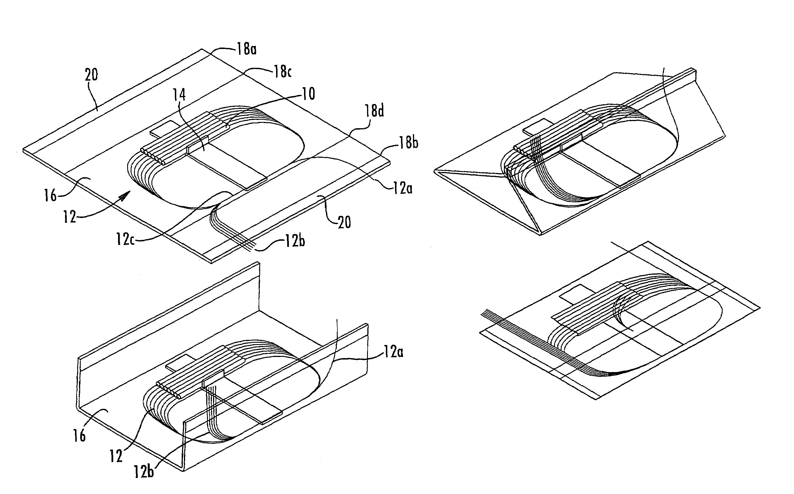
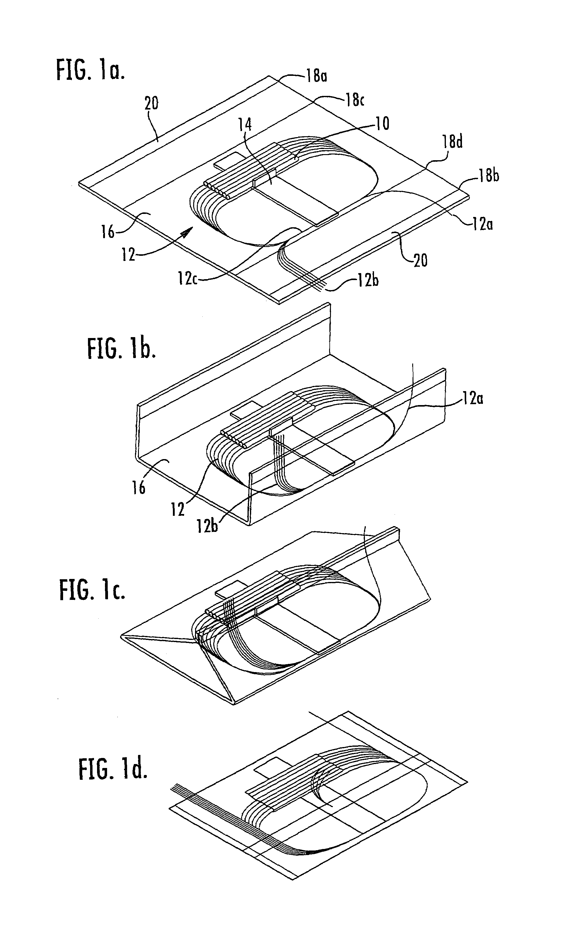
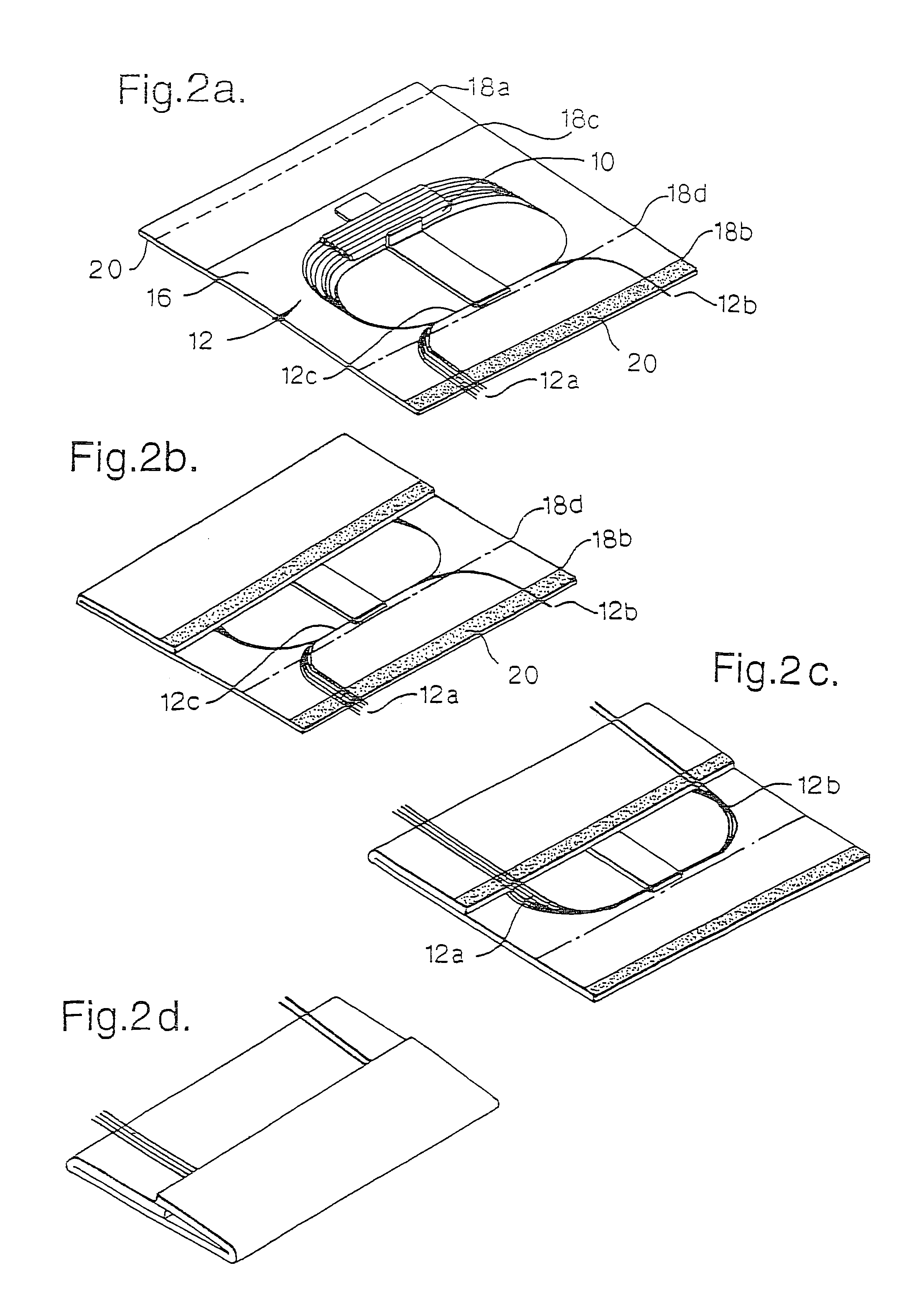
[0038]Referring to FIG. 1, a sealed enclosure for an optical component or components into which at least one optical fibre is fed is produced according to a first embodiment of the invention with reference to FIGS. 1a to 1d. In FIG. 1a an optical component comprising an array of splitters 10 and connected optical fibres 12 is mounted on a base plate support 14 with in-going fibres 12a and outgoing fibres 12b arranged in mirrored substantially S-shaped routes with straight sections 12c extending substantially parallel to the splitters 10 at the opposite end of the support 14. The arrangement of the optical component, fibres and support may be as described in the applicant's earlier GB patent application number 0129906.4. In FIG. 1a the optical component assembly is arranged on a flexible laminate sheet 16. The laminate sheet includes a moisture resistant barrier layer which is preferably made of aluminium. The laminate may be of the type used in Raychem's TDUX(™) products, as disclos...


PUM


Abstract

Enclosure and method for sealingly enclosing a space into and / or from which at least one optical fibre is fed to connect to at least one optical component, by providing a flexible protective sheet of substantially moisture resistant material having a pair of sealing strips; and folding and sealing the sheet around the optical component to provide an envelope enclosing the component with the optical fibre(s) sealed between the sealing strips. The invention also concerns an enclosure into and / or from which the optical fibres pass through an aperture which is sealed by all adherent patch or flap with the fibres sealed between the exterior surface of the enclosure and an overlying portion of the patch or flap.

Description

RELATED APPLICATIONS[0001]The present application is a National Phase application of PCT / GB03 / 01955 filed on May 7, 2003 and published in English, which claims priority from Application GB 0211517.8 filed on May 20, 2002, the disclosures of which are hereby incorporated by reference.FIELD OF THE INVENTION[0002]The present invention relates to optical fibre sealing. More in particular, the present invention relates to a method of and a device for sealingly enclosing a space into which one or more optical fibres are fed.BACKGROUND OF THE INVENTION[0003]It is well known that moisture has adverse effects on the properties of optical components. The split ratio of optical splitters, for example, may be influenced by the presence of moisture, and in optical connectors moisture may lead to increased losses. The sealing of optical components against moisture and other environmental influences, in other words environmental sealing, is therefore highly desirable.[0004]It has been proposed to ...

Claims


Application Information

Patent Timeline
IPC IPC(8): G02B6/00G02B6/36G02B6/44
CPCG02B6/4454G02B6/44
Inventor BELLEKENS, KATHLEENMEURS, PAULVANWINKEL, FREDDY
Owner TYCO ELECTRONICS RAYCHEM BVBA
Why Eureka
Eureka Blog
Learn More