Eureka AIR delivers breakthrough ideas for toughest innovation challenges, trusted by R&D personnel around the world.

Faucet assembly with integral water supply shut-off valve

Inactive Publication Date: 2006-08-24
SWIFTOP
View PDF21 Cites 6 Cited by
  • Summary
  • Abstract
  • Description
  • Claims
  • Application Information

AI Technical Summary

Benefits of technology

[0007] An object of the present invention is therefore to overcome the above mentioned drawbacks by providing a faucet assembly that is connected to sanitary fixtures such as sinks, washbasins, bidets, or the like, and allows an installer or service personnel to remove or replace a faucet head without the installer's having to manually shut off the water supply lines feeding the faucet assembly.
[0008] A particular object of the invention is to provide an automatic shut-off valve system that enables a faucet head to be easily mounted or removed from a faucet base, which is mounted on a sanitary fixture, without requiring that the installer climb or work from under the sanitary fixture.
[0009] Another object of the invention is to provide a device that enables the mounting of both conventional faucets and lever-type mono-control mixing valves and to enable their quick replacement.
[0010] A further object of the invention is to provide a device that can be manufactured at extremely low costs and thus will be very price-competitive in the marketplace.
[0014] A faucet apparatus for mounting on sanitary fixtures such as sinks, washbasins or the like, provides simple and quick installation of a faucet head without the need to manually shut off water supply lines. The apparatus comprises the faucet head and a fixture engaging base portion that is inserted into a through hole in the sanitary fixture and is with a portion thereof above the sanitary fixture. The faucet head is removable from the base, which stays attached to the sanitary fixture. A pair of passages or conduits extends through the base and are adapted to be connected below the sanitary fixture to water supply lines, and above the sanitary fixture for supplying the faucet head. The faucet apparatus further comprises automatic water supply shut-off valves disposed within the passages of the base and corresponding valve actuators disposed within the faucet head that allow quick and easy installation or removal of the faucet head assembly onto the sanitary fixture-engaging base without the need to manually turn the supply lines off and on. The shut-off valves are each comprised of a normally closed valve assembly that, when the faucet head is not present, remain in a closed position by the presence of water pressure from the supply lines or by spring tension. The faucet head assembly is comprised of a water dispensing unit, a pair of passages that align with the passages or conduits of the base, coupler fittings that engage with the faucet head passages at one end and with the base passages at a second end. The corresponding valve actuators are located on the second end of the coupler fittings. A plurality of o-ring seals affixed on the coupler fittings prevents undesired escape of water. When the faucet head is mounted on the base, the coupler fittings engage and seal against the base passages, and as the faucet assembly moves axially with respect to the base conduits, the actuators engage and open each valve assembly, enabling water flow to the faucet head as the faucet head is fully seated onto the base. In one embodiment of the faucet assembly, the base further comprises an additional passage for allowing installation of low-voltage conductors and electrical connections to enable features such as automatic faucet actuation. The faucet apparatus further comprises an attachment means for fixing the base portion to the sanitary fixture. The attachment means comprises a fixing member associated with the base and moved from an insertion position in which the fixing member is axially aligned with the hole in the sanitary fixture, and a locking position in which the fixing member is able to engage the lower surface of the sanitary fixture in which the hole is made.

Problems solved by technology

The mounting operation of conventional faucets to sanitary fixtures is troublesome in that an installer must necessarily work under the sanitary fixture where space is cramped and difficult to reach parts necessary to the installation.
Particularly in the case of sinks having two compartments, in which the through hole for the application of the faucet is placed at the partition between the two compartments, the mounting operation of the faucet is particularly difficult in that the installer must operate from the front of the sink whereas the faucet mounting hole is near the rear side between the two compartments which makes the access thereto particularly difficult.
In addition, the sanitary fixtures are usually placed resting against a wall, and the hole where the faucet is to be fixed, is proximate to this wall that hinders mounting operations of the faucet.
The mounting operations of faucets are also made complicated by the presence of a draining trap or column particularly when the faucet is installed onto a washbasin, as well as by the presence of the wall against which the sanitary fixture rests.
Further complicating installation of these faucets is the need to shut off the water supply lines feeding the faucet before installation or removal can be performed.
The supply lines must then be connected, or disconnected and reconnected for faucet replacement or repair, with the same accessibility difficulties as described above.
In any event, the mounting operation of faucets to sanitary fixtures is an awkward task in that the installer is compelled to work under the sanitary fixture itself.
The time required to properly install a faucet therefore contributes significantly to the cost of a project.

Method used


Image

  • Faucet assembly with integral water supply shut-off valve
  • Faucet assembly with integral water supply shut-off valve
  • Faucet assembly with integral water supply shut-off valve

Examples


Embodiment Construction

[0021] For a complete understanding of the features and operation of the present invention, reference is now made to the drawings of the invention along with the accompanying figures in which corresponding numerals in the different figures refer to corresponding parts of the invention.

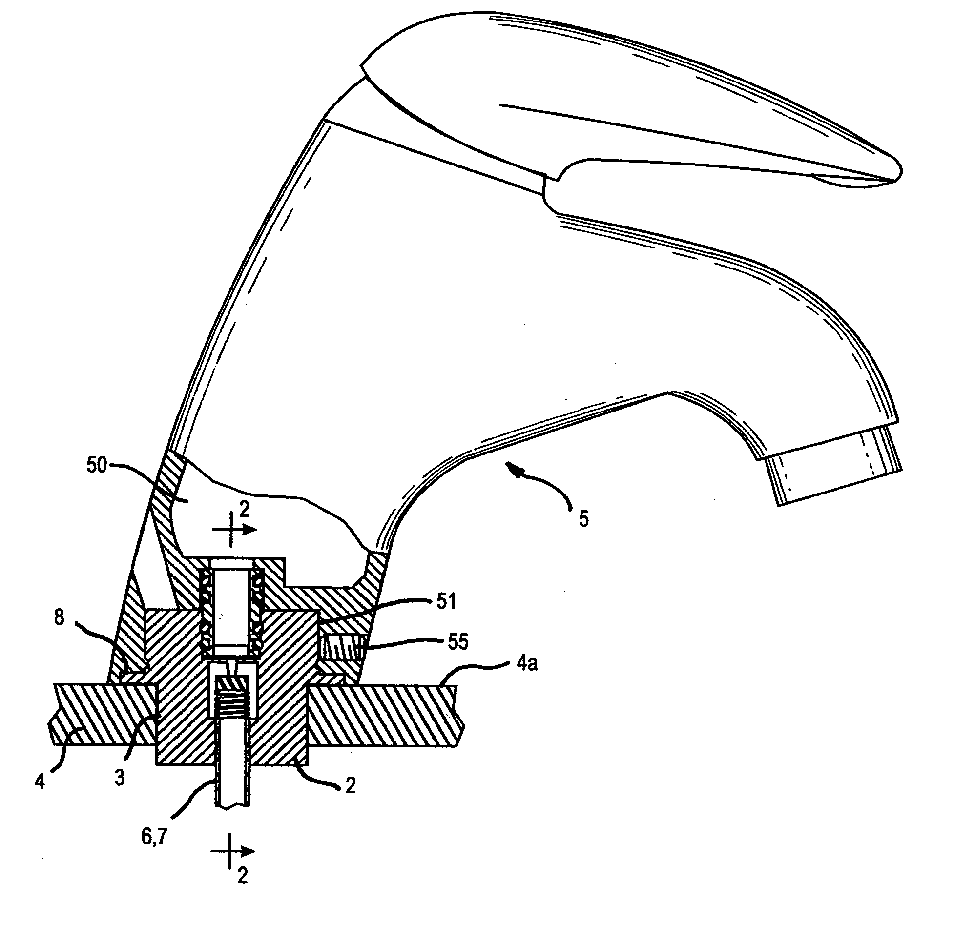
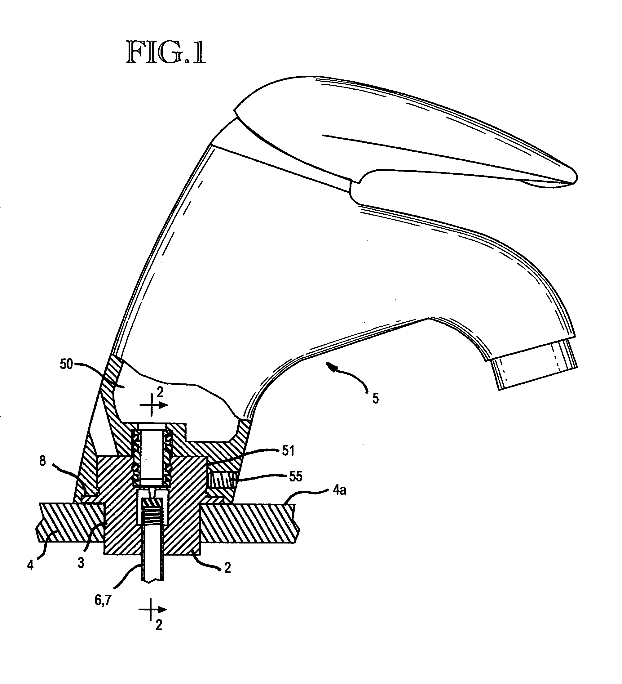
[0022] With reference to the above mentioned FIGS. 1-7, the apparatus comprises a base portion 2, which mounts within a through hole 3 defined in a sanitary fixture 4. Preferably, the sanitary fixture 4 is a sink, washbasin, bidet or the like. An upper portion of the base portion 2 protrudes above the sanitary fixture 4 and can be housed within a lower cavity 51 of the faucet apparatus 5, and is removably fixed thereto.

[0023] The base portion 2, preferably of a substantially cylindrical shape, is coupled coaxially in the through hole 3 so as to be aligned with a vertical axis and in a perpendicular attitude to a upper face 4a of the sanitary fixture 4.

[0024] A relatively narrow portion of the lower ...


PUM


Abstract

A faucet apparatus for mounting on sinks, washbasins and the like, is disclosed comprising automatic water supply shut-off valves that allow quick and easy installation or removal of a faucet head assembly on a faucet base mounted within a sink or similar fixture without the need to manually turn the supply lines off and on. The faucet head is removable from the base, which stays attached to the fixture. The shut-off valves are each comprised of a normally-closed valve assembly, and the faucet head has corresponding actuators that engage and open each valve assembly, enabling water flow to the faucet head as it is installed onto the base. The faucet apparatus further comprises an attachment means for mounting the base within a fixture. An alternate embodiment has a base comprising an additional passage for allowing installation of low-voltage conductors and electrical connections to enable features such as automatic faucet actuation.

Description

CROSS-REFERENCE TO RELATED APPLICATION [0001] This application claims priority to U.S. Provisional Patent Application No. 60 / 656,180, entitled FAUCET ASSEMBLY WITH INTEGRAL WATER SUPPLY SHUT-OFF VALVE,” filed Feb. 23, 2005.FIELD OF INVENTION [0002] The present invention relates generally to faucets for sanitary fixtures such as sinks, washbasins, bidets, or the like, and more particularly to a faucet assembly having a separable faucet head and a sanitary fixture-engaging base having automatic water supply shut-off valves that allow quick and easy installation of the faucet head onto the sanitary fixture-engaging base without the need to manually turn the supply lines off and on. BACKGROUND OF THE INVENTION [0003] As is known, faucets are generally applied to their respective sanitary fixtures by providing a through hole in a portion of the sanitary fixture where the faucet is to be applied, the base portion of said faucet being inserted into said through hole. In some kinds of fauce...

Claims


Application Information

Patent Timeline
IPC IPC(8): E03C1/04
CPCE03C1/0401E03C1/0403E03C2001/0416F16K43/005E03C1/04E03C1/05
Inventor HUBER, DONALD G.BROWN, SCOTT
Owner SWIFTOP
Why Eureka
Eureka Blog
Learn More