Grinding-disk receiving element especially for a hand-guided electric grinding tool

a technology of electric grinding tools and receiving elements, which is applied in the direction of grinding machine components, manufacturing tools, metal working apparatuses, etc., can solve the problem that the sanding disc cannot be installed in a faulty manner, and achieve the effect of simple installation

Active Publication Date: 2007-05-15
ROBERT BOSCH GMBH
View PDF4 Cites 84 Cited by
  • Summary
  • Abstract
  • Description
  • Claims
  • Application Information

AI Technical Summary

Benefits of technology

[0005]In contrast, a sanding-disc receiving element according to the present invention has the advantage that, due to the arrangement of the driving lugs and screw holes on a common circle around the central axis of the bearing flange, combined with the equidistant arrangement of adjacent driving lugs and screw holes, simple installation of a sanding disc is given, since there is a large number of ways to install it. At the same time, the sanding disc cannot be installed in a faulty manner, since the driving lugs always engage in a through hole in the sanding disc.
[0006]Due to the fact that the driving lugs are integrally joined with the bearing flange, the entire bearing flange can be produced in a single working step. This is advantageous, in particular, when the bearing flange and the driving lugs are composed of plastic, since only one tool is required to manufacture the entire bearing flange.
[0007]Due to the fact that the driving lugs have insertion bevels on their free ends, it is possible to insert these driving lugs in through holes in the sanding disc in a very simple and reliable manner, even if the sanding disc is rotated slightly relative to its end position on the bearing flange.
[0008]Due to the fact that the driving lugs and screw holes are arranged in an alternating manner on the circle, good driving of the sanding disc and its secure attachment to the bearing flange are ensured.
[0009]Due to the fact that the driving lugs and screw holes have essentially the same diameter, the through holes in the sanding disc can also have the same diameter. As a result, a larger number of possible fixing positions of the sanding disc on the bearing flange is obtained, and installation is simplified as a result.
[0010]Due to the fact that a cover disc fixes the bearing—which is located in a recess of the bearing flange—in the axial direction, a method for axially fixing the bearing is obtained in a very simple and economical manner. The bearing is also protected against dust. It is particularly advantageous when the cover disc engages, via an engagement part, in the recess of the bearing flange in the radial direction in a form-locked manner. A very good axial fixing of the bearing on the bearing flange is obtained as a result.

Problems solved by technology

At the same time, the sanding disc cannot be installed in a faulty manner, since the driving lugs always engage in a through hole in the sanding disc.

Method used


Image

  • Grinding-disk receiving element especially for a hand-guided electric grinding tool
  • Grinding-disk receiving element especially for a hand-guided electric grinding tool
  • Grinding-disk receiving element especially for a hand-guided electric grinding tool

Examples


Embodiment Construction

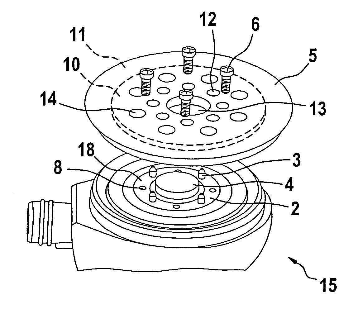
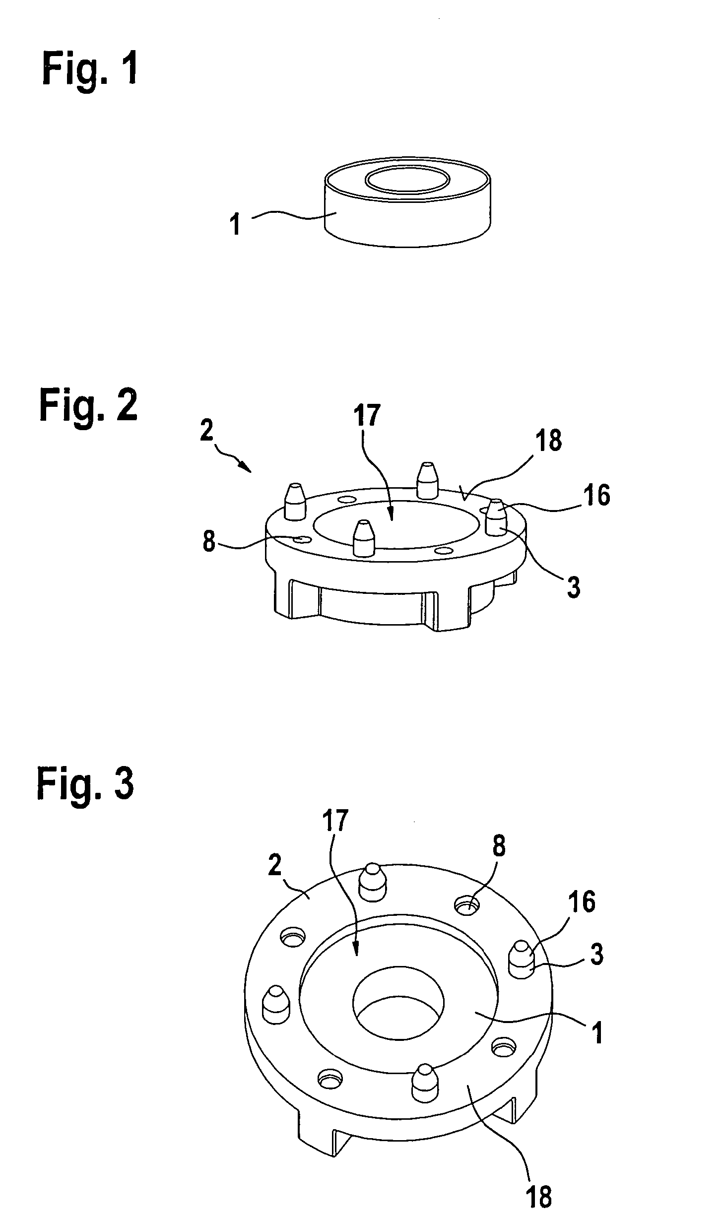
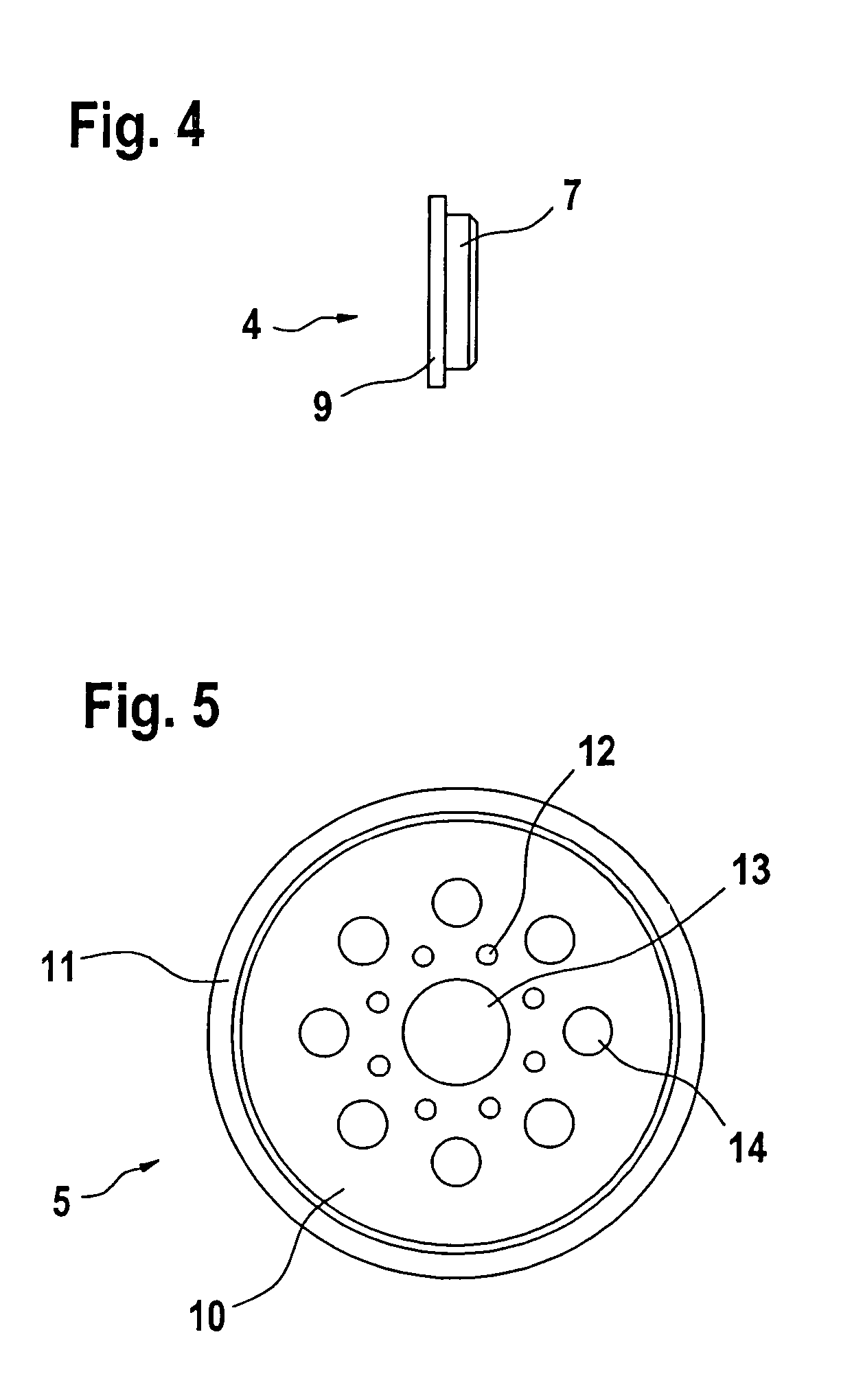
[0021]A bearing 1 in the form of a roller bearing is shown in FIG. 1. This bearing 1 serves to connect a drive axis of a hand-guided electric sanding tool with a sanding disc 5 (refer to FIGS. 5 through 7).

[0022]A bearing flange 2 according to the present invention is shown in FIG. 2. Four driving lugs 3 projecting outward in the axial direction are formed on its surface 18 facing sanding disc 5. Surface 18 also has four screw holes 8.

[0023]The spacial arrangement of driving lugs 3 and screw holes 8 is shown clearly in the view in FIG. 3, in which bearing 1 is radially fixed in a recess 17 of bearing flange 2 using a press fit.

[0024]Driving lugs 3 and screw holes 8 are arranged on a common circle around the central axis of bearing flange 2. The distances between adjacent driving lugs 3 and screw holes 8 are equal in every case. In addition, the driving lugs 3 and screw holes 8 are always arranged in an alternating manner on the circle. One screw hole 8 is therefore always located be...


PUM


Abstract

With a sanding-disc receiving element for a hand-guided electric sanding tool, an eccentric sander (15) in particular, the sanding-disc receiving element including a bearing flange (2) with a plurality of driving lugs (3) protruding in the axial direction around the surface (18), and a plurality of screw holes (8), and including a bearing (1) fixed in the axial and radial direction on the bearing flange (2), simple, reliable installation of the sanding disc (5) on the bearing flange (2) is ensured by the fact that the driving lugs (3) and the screw holes (8) are arranged equidistantly relative to each other on a common circle around the central axis of the bearing flange (2).

Description

CROSS-REFERENCE[0001]The invention described and claimed hereinbelow is also described in PCT / DE 2004 / 002126, filed Sep. 24, 2004 and DE 103 52 501.7, filed Nov. 11, 2003. This German Patent Application, whose subject matter is incorporated here by reference, provides the basis for a claim of priority of invention under 35 U.S.C. 119 (a)–(d).BACKGROUND OF THE INVENTION[0002]The present invention is directed to a sanding-disc receiving element for a hand-guided electric sanding tool.[0003]Sanding-disc receiving elements are known, with which a roller bearing is inserted into a two-part bearing flange, so that the roller bearing is clamped tightly between the two aluminum parts of the bearing flange in the axial and radial direction. This is accomplished using screws that engage through a sanding disc with screw holes in one of the two parts of the bearing flange. The second part of the bearing flange is clamped between the part of the bearing flange with the screw holes, and the sand...

Claims


Application Information

Patent Timeline
Patent Type & Authority Patents(United States)
IPC IPC(8): B24B23/03B24D99/00B24B23/04B24B45/00B24D9/08
CPCB24B23/04B24B45/00B24D9/08
Inventor FRECH, ALFREDLUTZ, TOBIAS
Owner ROBERT BOSCH GMBH
Why Eureka
Try Eureka