Ultra low pressure drop flow element system for measuring fluid flow rates

Inactive Publication Date: 2007-05-22
SCI IND NANO ENG
View PDF3 Cites 5 Cited by
  • Summary
  • Abstract
  • Description
  • Claims
  • Application Information

AI Technical Summary

Benefits of technology

[0008]Accordingly, several objects and advantages of the present invention will be presented in the following paragraphs followed by a thorough disclosure of each aspect in the accompanying embodiments in the DETAILED DESCRIPTION.
[0009]In light of the above-mentioned problems, it is therefore an object of the present invention to provide a device capable of creating minimal fluid turbulence;
[0010]Further, it is another object of the present invention to allow for high flow ra

Problems solved by technology

There is, however, a tendency for such devices to produce signals which are not consistently measurable, thus causing signaling devices of lesser accuracy than desired.
A drawback to existing differential pressure measuring flow meter systems is that the entire flow stream is typically necked-down into a redu

Method used


Image

  • Ultra low pressure drop flow element system for measuring fluid flow rates
  • Ultra low pressure drop flow element system for measuring fluid flow rates
  • Ultra low pressure drop flow element system for measuring fluid flow rates

Examples


Example

[0054]The following paragraphs will detail, at minimum, the best mode of the present invention. The exemplary figures and description of the invention as it is exemplified in each illustration is representative of the current invention and the scope of the invention disclosure is not intended to be limited by the exemplary teachings. One skilled in the pertinent art will readily recognize the possible variations and combinations of the embodiments that follow as this is intended to be within the scope of the taught flow element system for measuring fluid flow rates. Like physical structure in different figures share the same identifying numbers.

[0055]Advantages and disadvantages of utilizing differential pressure readings to determine a flow rate were discussed in the BACKGROUND OF THE INVENTION and SUMMARY OF THE INVENTION help establish attempts by others who have also realized the problems that the current invention is overcoming.

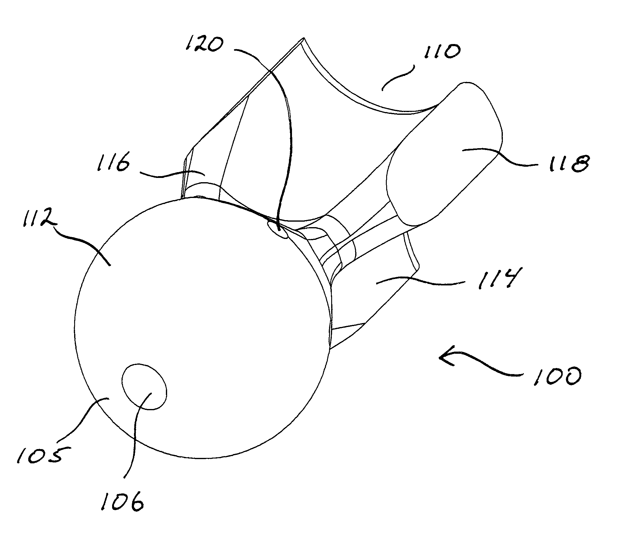
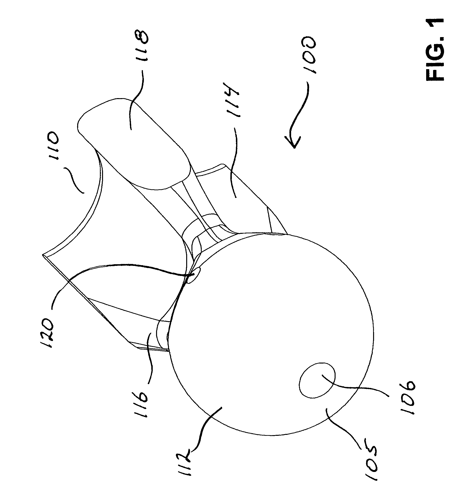
[0056]FIG. 1 illustrates an isometric frontal view...


PUM


Abstract

The present invention relates to the field of correlating a fluid flow rate by strategically measuring a differential pressure of a fluid. Embodiments of the present invention build off a simple concept of applying an aerodynamic device into a flow stream in conjunction with a flow concentrator and measuring fluid pressure at two locations on the aerodynamic device. The flow meter has not moving parts other than used for making tuning adjustments in some embodiments. A central design approach with the present invention is that each component can be adjusted relative to the other. Unlike prior systems that utilize a necked-down region of a fluid passage, the current system increases fluid velocities around a centralized flow element with the aid of an aerodynamic flow horn. Head losses are minimized through this approach. Additionally, having adjustability between the components will allow one to tune the flow meter to a preferred head loss and preferred pressure differentials by allowing the flow element to concentrically translate within its respective flow horn.

Description

CROSS REFERENCE TO RELATED APPLICATIONS[0001]Not applicable.FEDERALLY SPONSORED RESEARCH[0002]Not applicable.REFERENCE TO A MICROFICHE APPENDIX[0003]Not applicable.FIELD OF THE INVENTION[0004]The present invention relates to the field of correlating a fluid flow rate by strategically measuring a differential pressure of a fluid.BACKGROUND OF THE INVENTION[0005]The commercial value of a flow meter is dependent upon its ability to provide strong, clear signals which, for ease of use, are linearly related to fluid parameter signals, to be applicable to a variety of fluids each possessing unique viscosities and be usable over a large range of flow rates. There is, however, a tendency for such devices to produce signals which are not consistently measurable, thus causing signaling devices of lesser accuracy than desired. Many flow meters in a similar classification rely on the principles of Bernoulli's Equation, thus (usually) relating fluid velocities to fluid pressures. A drawback to e...

Claims


Application Information

Patent Timeline
IPC IPC(8): G01F1/37
CPCG01F1/40G01F1/42
Inventor BOWMAN, JOHN LLOYDSNIDER, ROSS JUSTIN
Owner SCI IND NANO ENG
Why Eureka
Try Eureka