Control valve having a curved spring hinge serving as a non-return valve

A technology for controlling valves and elastic bands, applied in the field of proportional valves, which can solve the problems of backflow of operating medium and damage to other components, and achieve the effect of high flow rate

Inactive Publication Date: 2013-01-02
SCHAEFFLER TECH AG & CO KG
View PDF6 Cites 5 Cited by
  • Summary
  • Abstract
  • Description
  • Claims
  • Application Information

AI Technical Summary

Problems solved by technology

Since other components, especially secondary components such as chain tensioners, etc. are usually connected to the same pressure oil circuit, the backflow of operating medium can cause damage to other components

Method used


Image

  • Control valve having a curved spring hinge serving as a non-return valve
  • Control valve having a curved spring hinge serving as a non-return valve
  • Control valve having a curved spring hinge serving as a non-return valve

Examples


Embodiment Construction

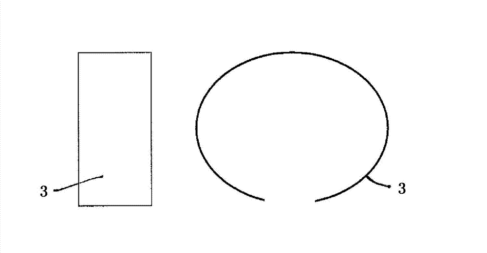
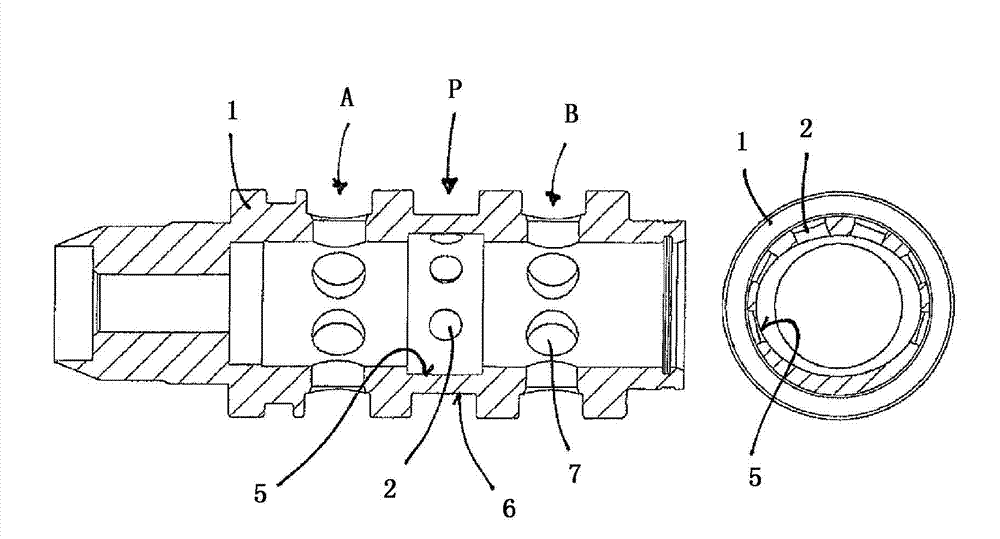
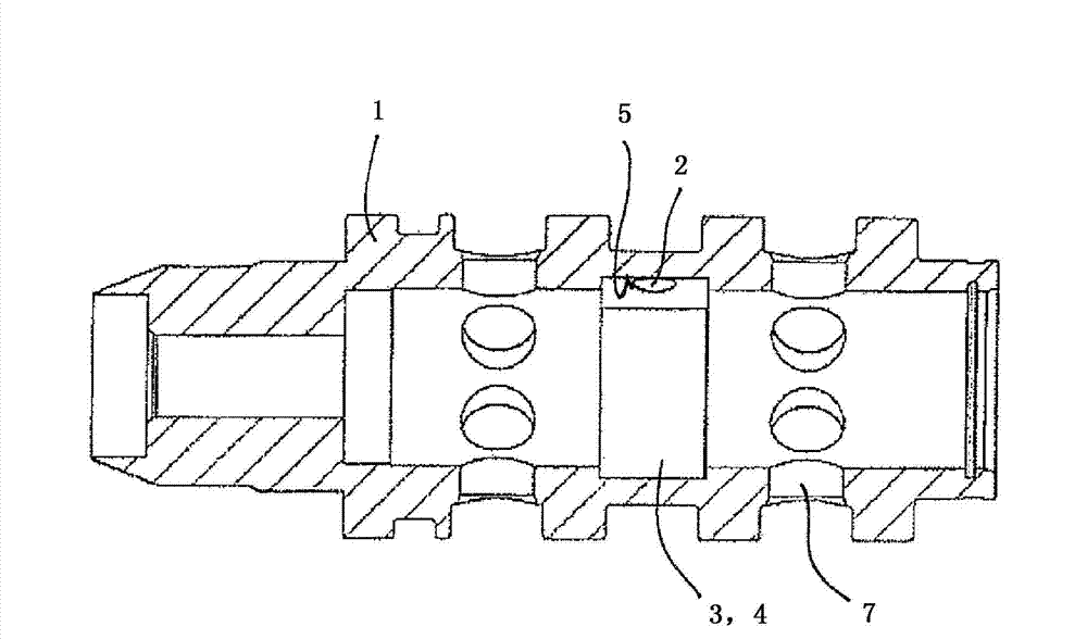
[0019] figure 1 and figure 2 The main elements of the control valve according to the invention, namely the elastic band 3 and the valve housing 1 , which can be used as check valve 4 , are each shown in a single view. exist image 3 and Figure 4 In the exemplary embodiment, the elastic strip 3 is inserted into the groove 5 on the valve housing 1 so that the elastic strip 3 bears against the groove 5 with a certain radial pretension. on the bottom of the tank.

[0020] as from figure 1 As can be seen in , the elastic strip 3, which can be used as a check valve 4, is bent into an oval shape so that the ends of the elastic strip 3 are spaced apart from each other. The spacing or opening between the ends of the oval shape ensures the elastic deformability of the elastic strip 3 inside the groove 5 . The width of the elastic strip 3 is constant and coordinated with the width of the groove 5 .

[0021] Such as figure 2 As shown, in the region of the opening 2 for hydrauli...


PUM


Abstract

The invention relates to a control valve, in particular a proportional valve for controlling a device for adjusting the rotation angle position of a camshaft with respect to a crankshaft of an internal combustion engine, comprising a hollow-cylindrical valve housing (1), which has a plurality of openings (2) that are arranged circumferentially in a radial plane for connecting to a pressure medium connection (P) and can be closed via a non-return valve (4) designed as a curved spring hinge (3). According to the invention, the openings (2) arranged in a radial plane are arranged at different angle distances to each other, and the shape and the rotation angle position of the curved spring hinge (3) serving as a non-return valve (4) is matched thereto.

Description

technical field [0001] The invention relates to a control valve, in particular a proportional valve for controlling a device for adjusting the rotational angular position of a camshaft of an internal combustion engine relative to a crankshaft, having the features of the preamble of claim 1 . Such a control valve has a cylindrically designed valve housing for accommodating an axially displaceable control piston, the axial displacement of which causes the pressure medium connection to be connected or disconnected from at least one working connection. For this purpose, the control piston has control edges on the outer peripheral side, which interact with openings of the valve housing arranged on the outer peripheral side. Background technique [0002] Control valves of the aforementioned type are used, for example, to control devices for adjusting the angle of rotation of a camshaft relative to a crankshaft of an internal combustion engine. The camshaft is used to actuate a ga...

Claims


Application Information

Patent Timeline
Patent Type & Authority Applications(China)
IPC IPC(8): F01L1/34F01L1/344F01L1/46
CPCF01L1/34F01L1/46F01L2001/34426F01L1/344F16K15/16
Inventor 延斯·霍佩拉斯·布赫曼
Owner SCHAEFFLER TECH AG & CO KG
Why Eureka
Try Eureka