Main rotor shaft mounted hydraulic pressure system

Active Publication Date: 2005-01-13
SIKORSKY AIRCRAFT CORP
View PDF14 Cites 5 Cited by
  • Summary
  • Abstract
  • Description
  • Claims
  • Application Information

AI Technical Summary

Benefits of technology

[0010] The present invention therefore provides a hydraulic pressure system for a rotor hub assembly which is powerful and generates

Problems solved by technology

These actuation systems provide numerous design challenges as significant power must be available to each rotor blade.
Disadvantageously, seals within the hydraulic slip ring may have an unacceptable service life.
The numerous feed and return lines which are required to power the

Method used


Image

  • Main rotor shaft mounted hydraulic pressure system
  • Main rotor shaft mounted hydraulic pressure system
  • Main rotor shaft mounted hydraulic pressure system

Examples


Embodiment Construction

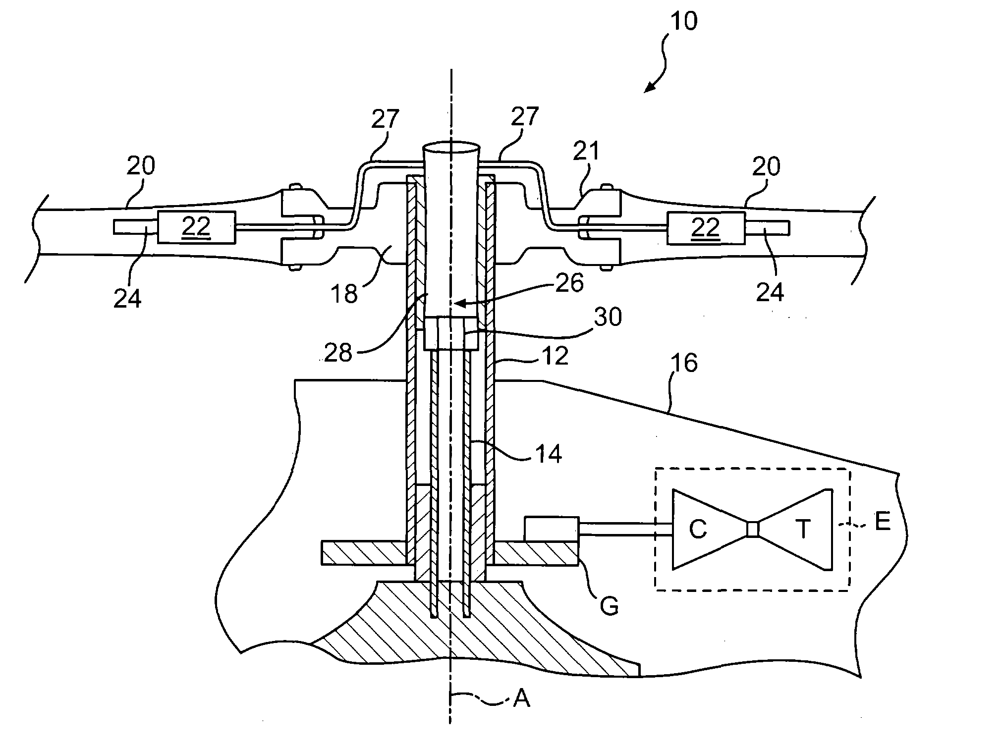
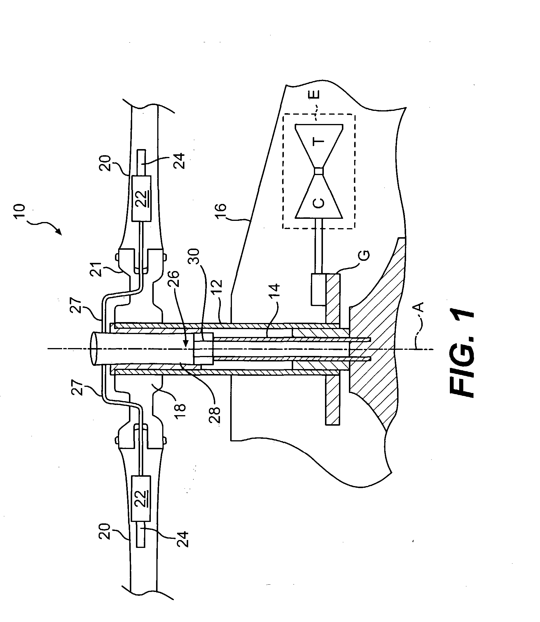
[0019]FIG. 1 illustrates a general schematic view of a rotor system 10. It should be understood that although a particular rotor system 10 is illustrated in the disclosed embodiment, other rotor systems for other vehicles such as helicopters, tilt-rotors, hybrid aircraft and conventional aircraft will also benefit from the present invention. A rotor shaft 12 is driven by an engine or engines E, typically through reduction gearing (illustrated schematically at G), for rotation about an axis of rotation A. The rotor shaft 12 is preferably a hollow tubular member and mounted concentric with a rotor standpipe 14. The standpipe 14 is rotationally fixed in position relative to a fuselage 16 and the rotor shaft 12 rotates about the standpipe 14.

[0020] A rotor hub 18 is mounted on the rotor shaft 12 for rotation therewith about axis A. The rotor hub 18 supports a multiple of rotor blades 20. Each rotor blade 20 preferably includes one or more hydraulically powered actuator systems (illustr...


PUM


Abstract

A rotor system includes a hydraulic pressure system located within a rotor shaft along an axis or rotation. The hydraulic pressure system is within the rotating field such that fluid pressure is generated and supplied from within the rotational field without the need to cross a rotational interface. Differential rotation between the rotor shaft and a standpipe rotates a hydraulic pump body relative a hydraulic pump shaft. The hydraulic pressure system is contained within a support structure so as to be readily mounted and removed from the rotor hub for replacement or maintenance. A gear system is mounted to the support structure between the standpipe and the hydraulic pump shaft to step-up or step-down the relative rotation between the rotor shaft and the standpipe.

Description

[0001] This invention was made with government support under Contract No.: NCC2-9016 awarded by the Department of the Army. The government therefore has certain rights in this invention.BACKGROUND OF THE INVENTION [0002] The present invention relates to a hydraulic pressure system mounted to a rotor hub assembly, and more particularly to a hydraulic pressure system mounted between a standpipe and a rotor shaft of a rotary wing aircraft. [0003] Multi-element airfoils are in common use on fixed wing aircraft. Such applications, however, are either in a fixed configuration or activate at relatively slow rates. In conventional applications, the aerodynamic flow environment is steady or quasi-steady conditions. [0004] Multi-element airfoil application to rotary-wing aircraft has concentrated upon individual blade control of each rotor blade wherein each rotor blade is pitched individually a multiple of times during each revolution of the rotor blade. Other multi-element applications util...

Claims


Application Information

Patent Timeline
IPC IPC(8): B64C27/32B64C27/615B64C27/64
CPCB64C27/32B64C27/615Y02T50/34B64C2027/7272B64C27/64Y02T50/30
Inventor LESKOW, DAVID J.EADIE, WILLIAM J.
Owner SIKORSKY AIRCRAFT CORP
Why Eureka
Try Eureka