Sewing machine embroidery thread guide

a technology of embroidery thread and guide, which is applied in the direction of embroidering machines, spool-pin assemblies, textiles and paper, etc., can solve the problems of tangling and breakage, operator back-space, and difficulty in preventing thread unraveling

Inactive Publication Date: 2007-05-22
TRONCOSO EVA G +1
View PDF13 Cites 16 Cited by
  • Summary
  • Abstract
  • Description
  • Claims
  • Application Information

AI Technical Summary

Benefits of technology

[0023](2) said attachment feature is achieved by means of a molded press-fit expandable cross-cut neck bell on said base mount that grips and secures the thread guide unit to the spool pin rod of a sewing / embroidery machine for the purpose of accommodating varying dimensional differences of spool pin rods by various home embroidery and sewing machine manufacturers. Another purpose of said gripping action is to permit vibration free feeding of thread without undue clatter or hesitation of the guide unit.(b) a free standing upwardly projecting laterally adjustable thread guide wire with an improved elliptically shaped eye on one end for the purpose of providing easy thread loading and tangle-free feeding of thread and a press-fit arrangement of coil windings on the lower / opposite end of said guide wire for the purpose of slideably gripping the transverse projecting slotted adjustment rod of the preferred embodiment. Said left / right adjustments are necessary to ascertain that the guide wire eye is centrally located and positioned for the purpose of feeding thread from the mid central area of said thread spool(s) to the consuming machine without tangling or pooling of the embroidery thread.
[0024]The basic simple version is comprised of a base-mount and a bendable wire or flexible memory material thread guide fitted with a pigtail or thread guide eye on one end for easy thread loading and smooth dispensing of embroidery thread. Preferably, the guide wire is “L” shaped and is affixed to a base mount while projecting either straight across from said base or angled upwardly for the purpose of allowing and making wire bend adjustments of the thread guide eye. The purpose for the preferred positioning of the guide eye is to control and funnel the embroidery thread material so that the thread feeds continually from the central mid-point area of the thread spool to the consuming machine.
[0025]To facilitate and speed up the threading process on a sewing / embroidery machine, the embroidery thread guide of the present invention has a loop shaped pig-tail shaped eye on one end of the guide wire. The most dissimilar and striking differences of the preset invention over any prior art is the method of attaching and mounting the thread guide onto a home embroidery and sewing machine utilizing the machine spool pin rod along with the novel central positioning of the guide eye mentioned and described in the preceding paragraph. The purpose of the spool pin rod attachment procedure is to affix the thread guide to said machine for the purpose of assuring absolute and constant feeding of embroidery thread via the guide eye from the central mid-point area of the supply spool to the consuming machine. This application positively prevents and eliminates any and all pooling or tangling of thread on all home embroidery and sewing machines regardless of thread spool designs utilized.
[0026]Simultaneously, the new thread guide shortens the length of span and spacing that exists between the thread spool and the external or internal take-up lever of a machine. This application and procedure also serves to introduce and apply the element of friction to the thread line by the calculated placement of the guide eye within close proximity of the dispensing thread spool which creates and applies a small amount of increased line drag and friction to the slippery embroidery thread as it leaves the spool to feed the consuming embroidery machine.
[0027]A general explanation and comparison would be taking a dog for a walk using a lengthy leash whereby the dog can trip, wind itself around a pole or trip the owner with the lengthy leash. On the other hand, a dog owner with a short leash has improved control over his animal by the advantage of the shorter leash and the accompanying reduced leash slack.

Problems solved by technology

Instead, practically every embroidery person realizes that the operator must maintain a watchful vigil on a home embroidery and sewing machine or suffer the consequences of constant tangling and breakage when using rayon thread.
In addition to said aforementioned inconveniences, the operator is also required to back-space to the area of the garment / material where the stitching and stitches left off before the thread jam and breakage occurred.
The purpose of re-doing the last embroidery stitches is due to the fact that many stitches are lost due to said thread breakage problems.
It is also a fact that most problems encountered and associated with embroidery and tangling, are due to the slick nature of the rayon thread material itself.
The slicker and more slippery the material, the more difficult it becomes to prevent the thread from unraveling and sliding off of the reel portion of the thread spool.
This frustrating malady, occurs as the machine embroiders and as the thread is being fed and dispensed to the machine from a spool.
The same tangling and thread problems are known to exist when using slick metallic embroidery thread.
The physical weight of the slippery thread itself is sufficient to cause the thread to sag and unravel and thus fall off the spool which accounts for undesirable pooling and piling of thread at the base of said reel / spool.
Furthermore, the physical length and girth of each thread spool varies with each manufacturer which further compounds said thread feeding and tangling problems.
It is well known that most thread spools are made without beveled core lips on the spool ends and are known to cause most pooling and tangling problems.
Prior art devices have not adequately solved the problems.
However, the operator is still required to thread the machine individually, one spool at a time, for each and every thread color change when working with either of the two aforementioned carousel type devises.
To the dismay of embroidery fans throughout the world, the continuing tangling problems have not been solved nor eliminated by the prior art.
Such criteria have not been met with other conventional thread guides or prior art.

Method used


Image

  • Sewing machine embroidery thread guide
  • Sewing machine embroidery thread guide
  • Sewing machine embroidery thread guide

Examples


Embodiment Construction

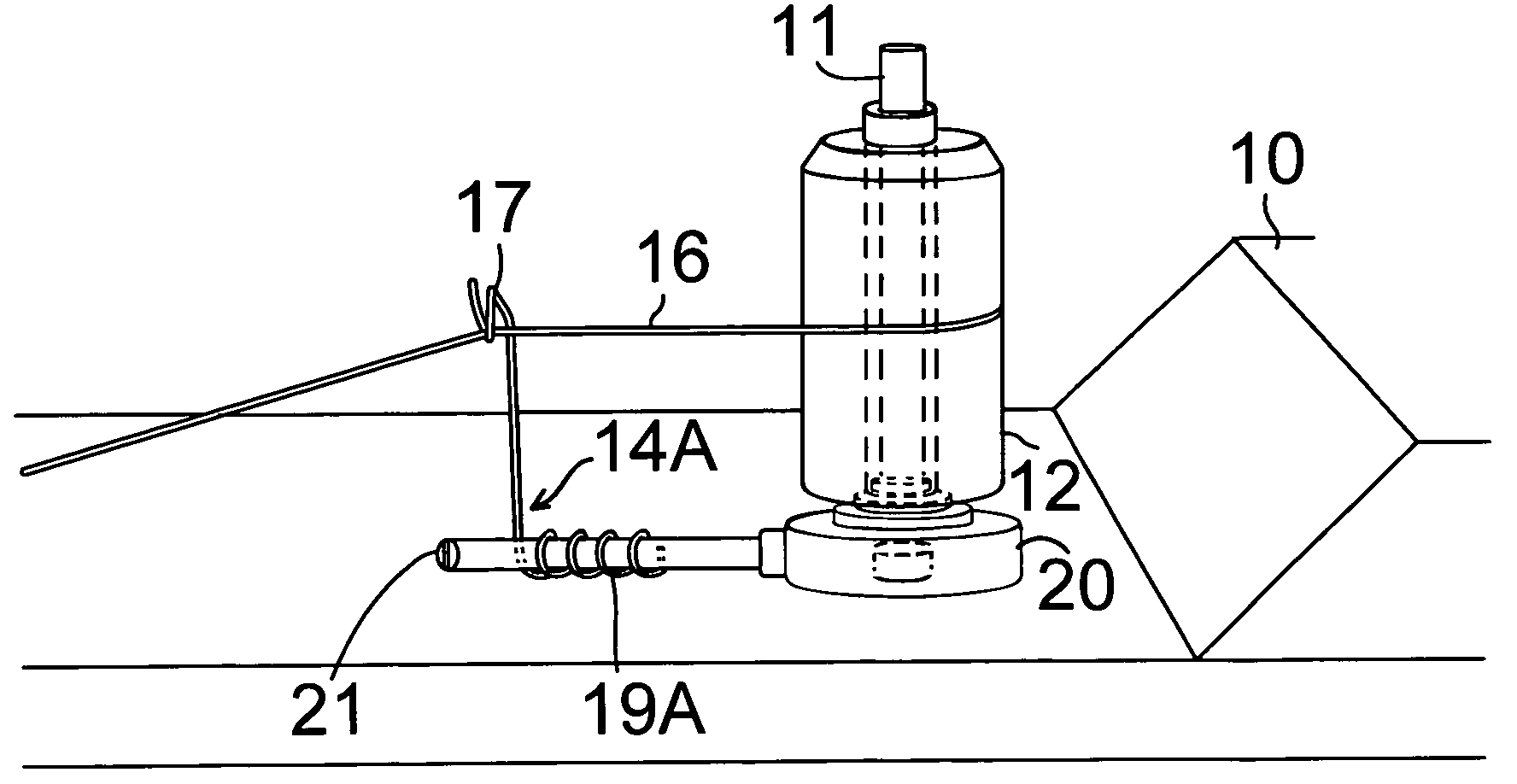
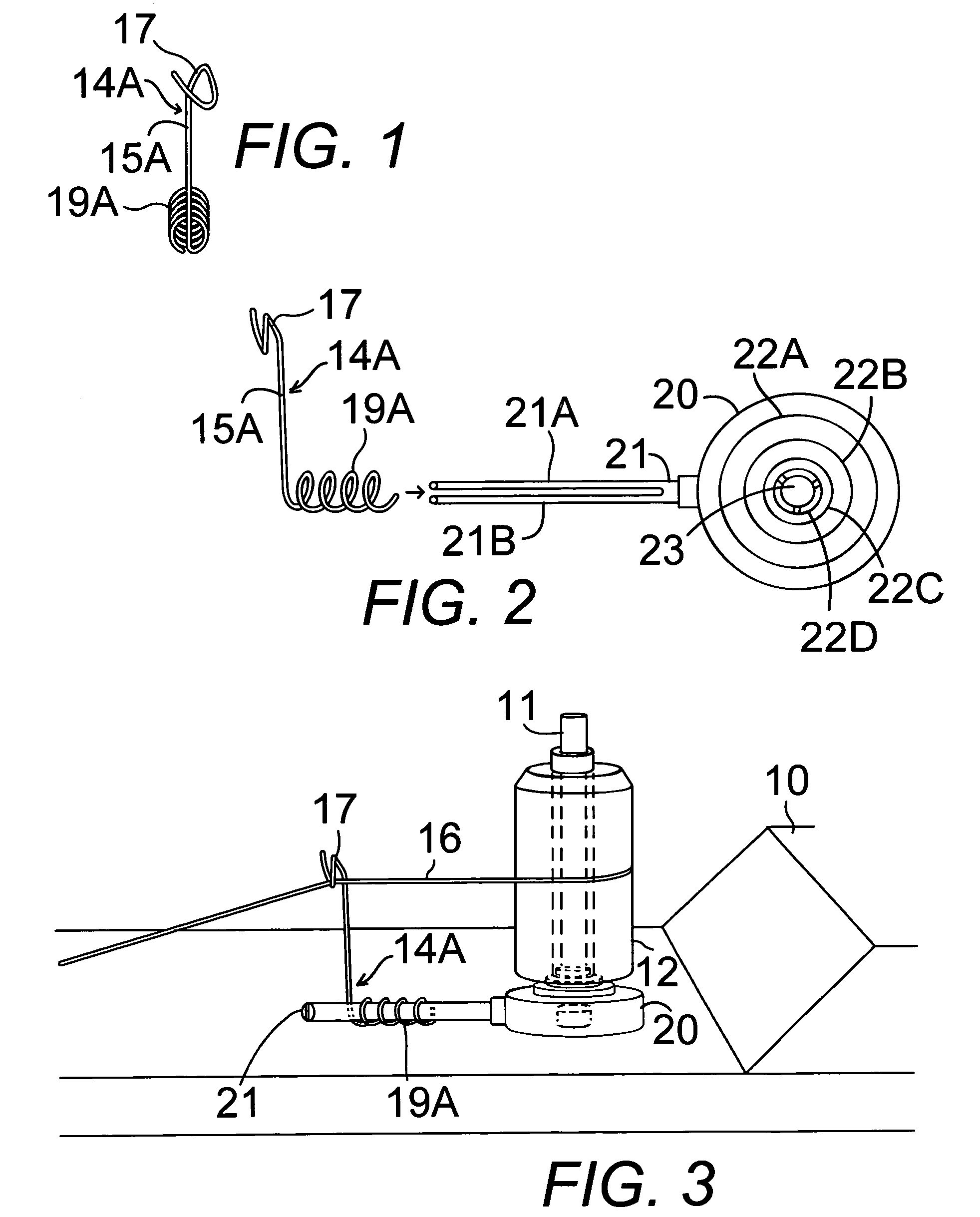
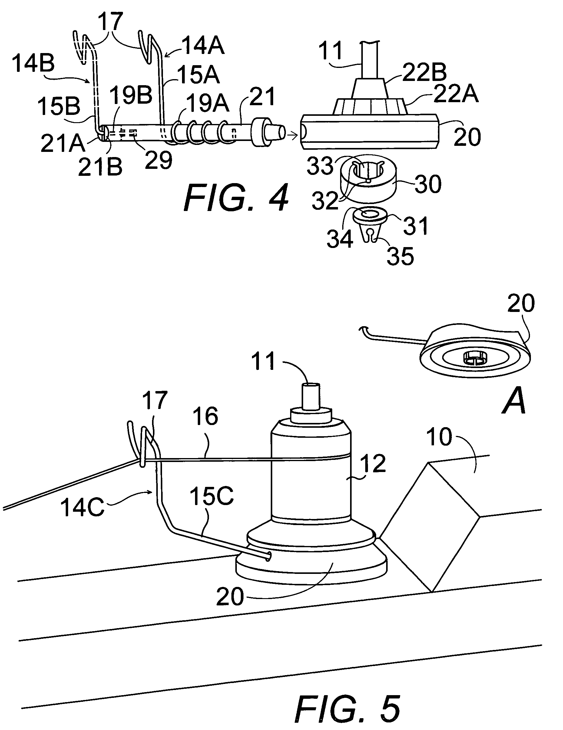
[0045]In FIGS. 1–10, a thread guide attachable to an embroidery and sewing machine spool pin rod 11 comprises a thread guide arm 14A–14C attached by a base mount 20 for guiding embroidery thread 16 from an embroidery spool 12 on the spool pin rod 11 of an embroidery and sewing machine 10.

[0046]The thread guide arm 14A–14C comprises an upwardly projecting element, preferably a bent wire 15A–15C with an open loop 17, preferably an open spiral bend, at a distal end of the bent wire. The thread guide arm is adapted to generally extend along a forward-rearward axis of an embroidery and sewing machine 16 with the open loop spaced apart from and positioned opposite to a central portion of an embroidery thread spool 12 of an embroidery and sewing machine 10, as seen in FIGS. 3, 5, and 6. The open loop 17 is adapted to receive a line of embroidery thread 16 through the open loop 17 with the line of embroidery thread 16 extending from the embroidery thread spool 12 on one side of the thread g...


PUM


Abstract

A bent embroidery thread guide wire is attached to a base mount releasably attachable to a spool pin rod of an embroidery and sewing machine. An open spiral bent loop end of the upwardly bent wire adjusts to a position spaced slightly apart from and approximately centered on an embroidery thread spool mounted on the machine. The embroidery thread feeds from the spool through the open looped end, through the normal threading procedure of the machine, to the thread consuming needle apparatus under tension. A transverse bar extending from the base mount allows the guide wire to slide adjustably thereon to move toward or away from the spool. A stepped base mount receives embroidery thread spools of different diameters.

Description

BACKGROUND OF THE INVENTION[0001]1. Field of the Invention[0002]The present invention relates to an improved thread guide for home embroidery and sewing machines and equipment, and more particularly, to an improved thread guide for the purpose of preventing undesirable unraveling and tangling of the thread which occurs while sewing and doing embroidery work with slippery rayon or metallic thread on home embroidery and sewing machines.[0003]2. Description of the Prior Art[0004]The art of sewing is as old as mankind and goes back more than 20,000 years. The first functional sewing machine in America was invented and patented by Elias Howe. However, it was Isaac Singer who designed and built the first commercially successful sewing machine during the 1850's. Inevitably, the two American inventors fought bitter legal battles resulting with Howe emerging victorious in a court case against Isaac Singer for infringement of the Howe patent.[0005]In spite of having to pay royalties to Howe f...

Claims


Application Information

Patent Timeline
Patent Type & Authority Patents(United States)
IPC IPC(8): D05C3/00
CPCD05B43/00
Inventor TRONCOSO, EVA G.TRONCOSO, FREDDIE
Owner TRONCOSO EVA G
Why Eureka
Try Eureka