Cut valve with check valve

a check valve and valve body technology, applied in the field of cut valves with check valves, can solve the problems of affecting the quality of the product, and the manufacturing cost of the product, so as to reduce the cost of materials, prevent leakage of fuel vapor, and facilitate the effect of efficient and fast operation

Active Publication Date: 2007-05-22
PIOLAX CO LTD
View PDF7 Cites 15 Cited by
  • Summary
  • Abstract
  • Description
  • Claims
  • Application Information

AI Technical Summary

Benefits of technology

[0010]Accordingly, an object of the invention is to provide a cut valve with a check valve, which is enabled to easily and efficiently perform an operation of assembling the body thereof and to reduce the manufacturing cost thereof and which excels in durability thereof.
[0023]The cut valve with the check valve according to embodiments of the invention is configured by disposing the positive pressure valve, the negative pressure valve, and the springs for pressing the pressure valves on the body case, and by making the pressure valves and the springs to be covered with and fitted into the cap member. Thus, an operation of assembling the body thereof can be easily and efficiently performed. Also, because the positive pressure valve and the negative pressure valve are made of resin, the cost of materials thereof can be reduced. Thus, stable performance thereof can be maintained for a long time. Furthermore, the body case and the cap member are constituted separately from each other. Thus, the body case may be formed of materials, for example, polyamide and polyacetal, which excel in dimensional stability, strength and fuel nonpermeability. The cap member may be made of materials, for instance, polyethylene and polypropylene, which can be welded to the fuel tank.

Problems solved by technology

Therefore, this device has a problem in that the operation of assembling the case body takes time and trouble.
Further, because at least one of the first valve member and the second valve member is formed of a rubber in the fuel shut-off device disclosed in U.S. Pat. No. 5,582,198, the manufacturing cost thereof rises.
There is the possibility of swelling and deteriorating the rubber due to the fuel.

Method used


Image

  • Cut valve with check valve
  • Cut valve with check valve
  • Cut valve with check valve

Examples


Embodiment Construction

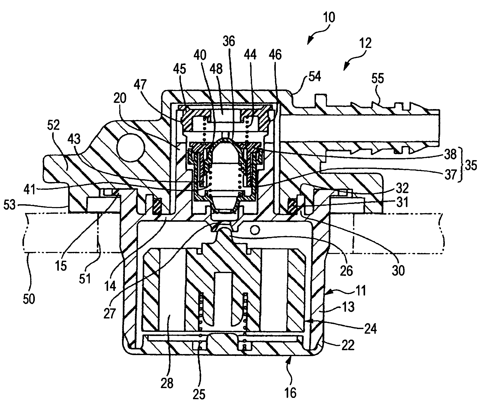
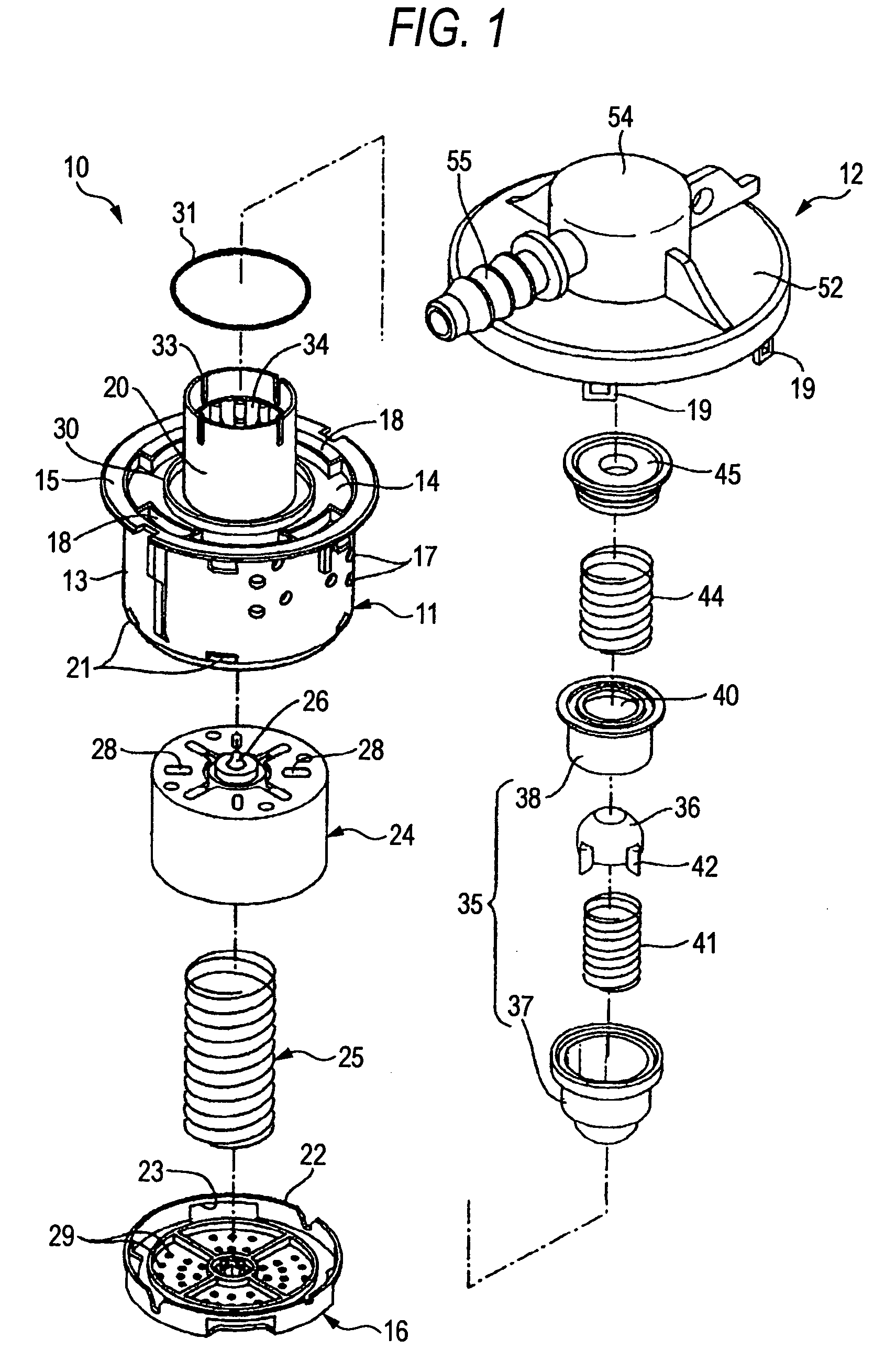
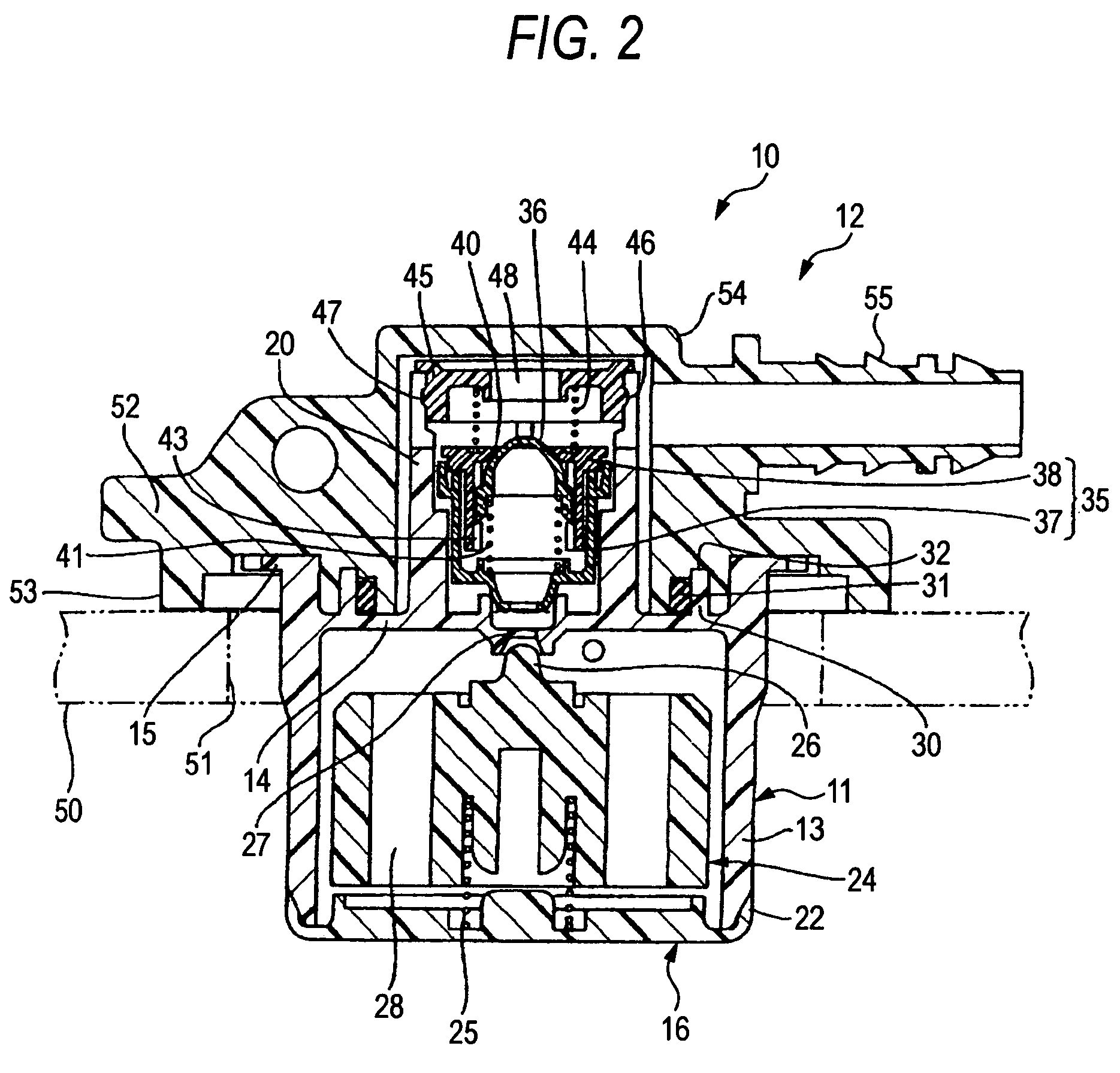
[0033]Hereinafter, embodiments of the invention will be described with reference to the accompanying drawings. FIGS. 1 to 5 show a cut valve with a check valve according to an embodiment of the invention.

[0034]As shown in FIG. 1, a cut valve 10 with a check valve mainly includes a body case 11 and a cap member 12. The body case 11 has a cylindrical peripheral wall 13 and a top wall 14. A flange portion 15 is formed along the peripheral edge of the top wall 14. The bottom surface of the peripheral wall 13 is opened. A bottom cover 16 (described later) is fitted to this bottom surface of the peripheral wall 13. Plural through holes 17 are defined in the peripheral wall 13. The through holes 17 serve as holes through which fuel vapor and fuel pass. Plural insertion holes 18 are defined in a continuous connection portion between the flange portion 15 and the top wall 14 at predetermined intervals in a circumferential direction. These insertion holes 18 serve as portions, in each of whic...


PUM


Abstract

A cut valve with a check valve includes a body case, a cap member, positive and negative pressure valves, and first and second springs. The body case defines a vent hole. The cap member is fitted to an upper portion of the body case. The positive pressure valve is made of resin, defines an opening part, and is disposed to be contactable with and separable from the vent hole from above. The first spring is disposed on the positive pressure valve and presses the positive pressure valve in a direction in which the positive pressure valve closes the vent hole. The negative pressure valve is made of resin and is disposed to be contactable with and separable from the opening part from below. The second spring presses the negative pressure valve in a direction in which the negative pressure valve closes the opening part.

Description

BACKGROUND OF THE INVENTION[0001]1. Field of the Invention[0002]The present invention relates to a cut valve with a check valve attached to a fuel tank of, for example, an automobile and including a cut valve for preventing fuel, which is shaken by a turn and a tilt of the automobile, from leaking out of the tank, and a check valve for feeding fuel vapor to a canister according to the internal pressure of the tank.[0003]2. Description of the Related Art[0004]A cut valve for preventing fuel, which is shaken by a turn and a tilt of an automobile, from leaking out of a fuel tank of the automobile is attached thereto. Further, a communication hole opened and closed by this cut valve is connected through a check valve to a canister disposed outside the tank. Furthermore, the check valve is connected through a pipe to the canister.[0005]Especially, in the case of a resin fuel tank, a cut valve is attached to an opening portion defined in an upper wall of the tank by, for example, welding....

Claims


Application Information

Patent Timeline
Patent Type & Authority Patents(United States)
IPC IPC(8): F16K17/196B60K15/077F02M37/00
CPCF16K17/196Y10T137/0874Y10T137/3087Y10T137/3099Y10T137/7774Y10T137/7841
Inventor FURUYA, MASASHIMATSUO, SHINICHI
Owner PIOLAX CO LTD
Why Eureka
Try Eureka