Vibration-proof zoom lens and camera provided with the same

a technology of vibration-proof zoom and lens, which is applied in the field of vibration-proof zoom lens and camera, can solve the problems of large eccentric aberration and lack of lens structure suitable, and achieve the effect of effectively preventing the deterioration of image quality and high zoom ratio

Active Publication Date: 2007-05-22
FUJI PHOTO OPTICAL CO LTD
View PDF14 Cites 12 Cited by
  • Summary
  • Abstract
  • Description
  • Claims
  • Application Information

AI Technical Summary

Benefits of technology

[0006]It is a second object of the present invention to provide a vibration-proof zoom lens in which aberration is restrained from fluctuating at a time of zooming.
[0007]It is a third object of the present invention to provide a vibration-proof zoom lens in which it is possible to effectively relieve image blur to be caused by vibration.
[0011]Moreover, each of the negative front group and the positive rear group is composed of a single lens. In this case, a structure for moving the lens in a direction perpendicular to the optical axis is simplified, and force required for moving the lens is small. Thus, the lens structure performs a practical vibration-proof function.
[0014]The fourth lens group includes a negative lens having a concave facing toward the subject side, a positive lens having a convex facing toward the image side, and a biconvex positive lens. Either surface of the biconvex positive lens is an aspherical surface whose convex power becomes stronger toward its periphery. By virtue of this, fluctuation of aberration is restrained in both of long-distance shooting and short-distance shooting so that it is possible to obtain the vibration-proof zoom lens capable of performing excellent focus adjustment.
[0015]The second lens group comprises a negative meniscus lens, a cemented lens of a positive lens and a negative lens, a positive lens whose convex faces toward the subject side, and a negative lens, which are disposed in this order from the subject side. A concave of the negative meniscus lens faces toward the image side. The positive lens of the cemented lens has a convex facing toward the image side. By virtue of this, the vibration-proof zoom lens has excellent image-forming performance regarding resolution and contrast of the whole magnification range.
[0017]According to the present invention, it is possible to obtain the high-performance vibration-proof zoom lens in which an angle of view is 70 degrees at the wide-angle end, and brightness of F1.9 and high zoom ratio of 11 times are achieved. Further, in this zoom lens, image quality is effectively prevented from deteriorating due to vibration, and aberration fluctuation is properly corrected at a magnification changing time and a focusing time.

Problems solved by technology

However, large eccentric aberration occurs when the certain lens is moved in the direction perpendicular to the optical axis.
Thus, there is a problem in that the zoom lens of the Publication No. 7-151967 does not have a lens structure suitable for conferring the vibration-proof function.

Method used


Image

  • Vibration-proof zoom lens and camera provided with the same
  • Vibration-proof zoom lens and camera provided with the same
  • Vibration-proof zoom lens and camera provided with the same

Examples


embodiment 1

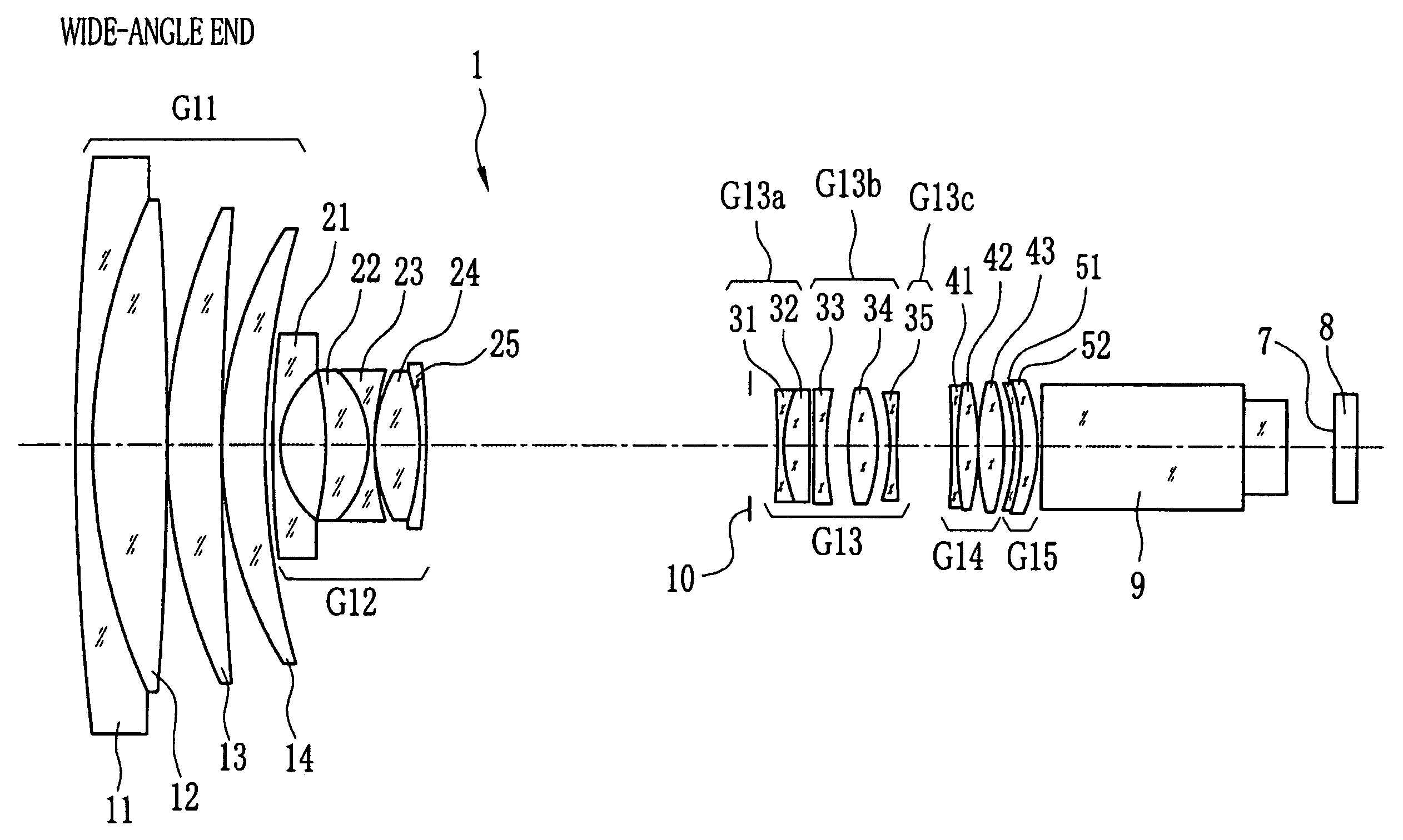
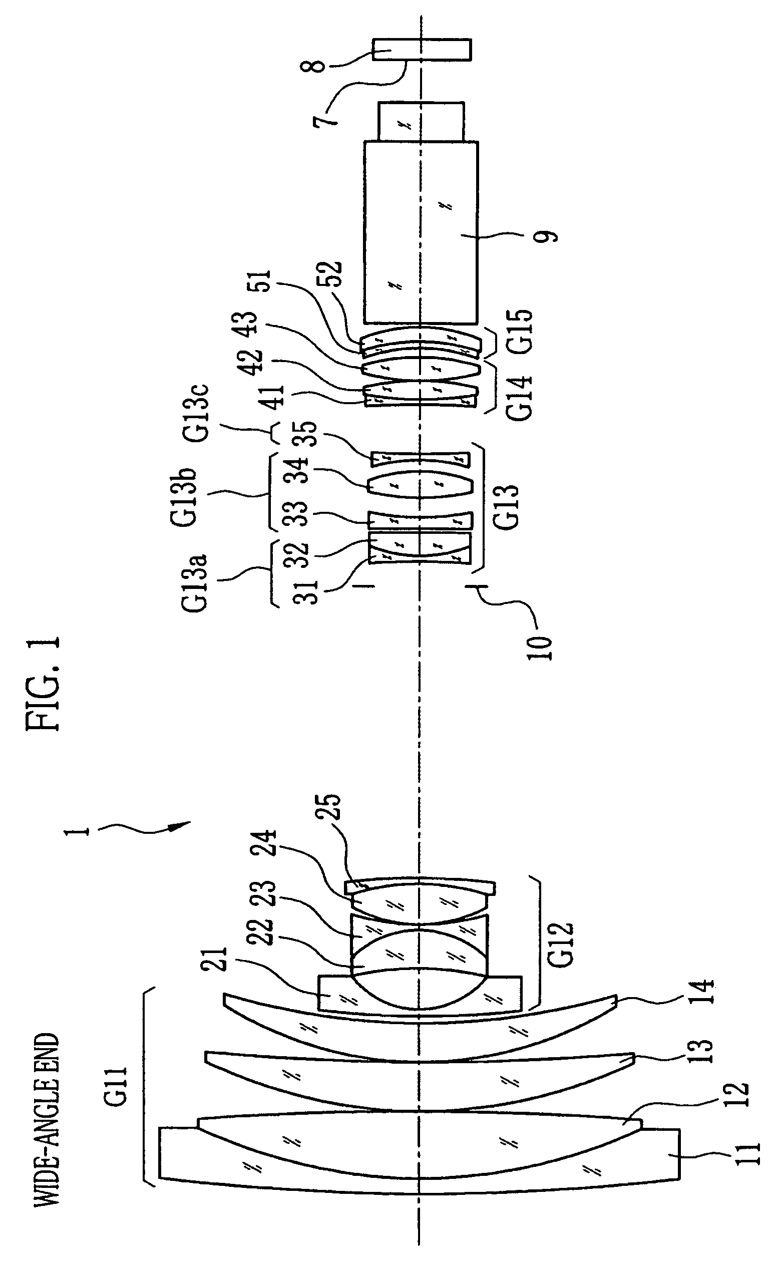
[0033]In FIGS. 1 and 2, a vibration-proof zoom lens 1 comprises a first lens group G11 having positive power, a second lens group G12 having negative power, a third lens group G13 having positive power, a fourth lens group G14 having positive power, and a fifth lens group G15 having positive power, which are disposed in this order from a subject side of the zoom lens 1. The second lens group G12 moves toward an image side of the zoom lens 1 when magnification is changed from a wide-angle end to a telephoto end. At this time, the fourth lens group G14 moves to correct variation of an image plane 7, on which an image of a subject is formed, in an optical-axis direction. The variation of the image plane is caused in accordance with the magnification change. Also, the fourth lens group G14 moves in the optical-axis direction to perform focus adjustment. The first, third and fifth lens groups G11, G13 and G15 are fixed and positions thereof are constant at any time including the magnific...

embodiment 2

[0042]

TABLE 4ACurvatureSurfaceRefractiveAbbeRadius RInterval DIndex NeNumber ν d126.47270.3351.85503723.8210.23071.4241.49845781.63−1530.23080.017410.22721.0301.73600254.7551.33390.01768.02310.7911.73225655.0715.4617Variable816.34040.1341.88814040.891.77420.91010−11.07840.8181.85888922.511−2.11350.1361.81904446.5124.77810.017132.82820.6901.53833148.3141317.78360.1361.88511040.01531.1205Variable16Stop0.5501719.12750.1341.52141259.2183.13540.4491.85832722.519113.91950.084

[0043]

TABLE 4BCurvatureSurfaceRefractiveAbbeRadius RInterval DIndex NeNumber ν d*20 65.59450.2681.69416531.1217.68780.537225.49650.8311.50060165.023−2.78720.14224−10.09840.1341.85874522.5254.4091Variable26−3.68730.1341.60482138.9275.48940.5371.50177265.028−3.49810.017*29 3.67800.5801.66155658.630−6.1531Variable31−14.09340.1341.85495223.932−31.52050.2231.88814040.833−13.04290.08434Infinity4.0171.60718138.035Infinity0.8451.51825064.136Infinity

[0044]In FIGS. 4 and 5, a vibration-proof zoom lens 2 comprises first through ...

embodiment 3

[0049]

TABLE 7ACurvatureSurfaceRefractiveAbbeRadius RInterval DIndex NeNumber ν d 124.03690.3351.85503723.8 210.42041.4651.49845781.6 3−422.81340.017 410.28821.0241.65955658.7 544.70650.017 68.06490.8511.69494656.9 718.0344Variable 822.53580.1341.88814040.8 91.79270.90210−7.05810.6671.85888922.511−2.38290.1361.76646551.7124.75260.017133.02330.6571.59709338.714−565.48210.1361.88511040.01533.2075Variable16Stop0.549175.72430.1341.79823345.3182.61180.4631.85848022.51920.10180.167*20 18892.91560.2581.69416531.1218.74670.500224.85540.5481.49785465.223−2.90340.11924−16.85930.1341.85873022.5254.4350Variable26−2.58460.1341.61628238.0276.38420.6331.50041665.128−2.59110.017

[0050]

TABLE 7BCurvatureSurfaceRefractiveAbbeRadius RInterval DIndex NeNumber ν d*29 3.74810.6031.63931559.730−6.3195Variable31−12.22650.1341.85495223.932−21.70480.2041.88814040.833−11.43950.08434Infinity4.0171.60718138.035Infinity0.8451.51825064.136Infinity

[0051]In FIGS. 7 and 8, a vibration-proof zoom lens 3 comprises first ...


PUM


Abstract

A vibration-proof zoom lens comprises a positive first lens group, a negative second lens group, a positive third lens group, a positive fourth lens group, and a positive fifth lens group, which are disposed in this order from a subject side. The second lens group moves toward an image side at a time when magnification changes from a wide-angle end to a telephoto end. The fourth lens group moves to correct variation of an image plane at the time of magnification change. The first, third and fifth lens groups are fixed. The third lens group is composed of first to third subgroups. When vibration occurs, the second subgroup is moved in a plane perpendicular to an optical axis to correct an image position so that an image blur is prevented.

Description

FIELD OF THE INVENTION[0001]The present invention relates to a vibration-proof zoom lens and a camera provided with the same, which is suitable for an electronic camera of a broadcasting camera or the like, and to which a vibration-proof function is conferred to prevent an image from blurring due to camera shake.BACKGROUND OF THE INVENTION[0002]A zoom lens of a rear focus type is known (see Japanese Patent Laid-Open Publication No. 7-151967, which is a counterpart of Japanese Patent No. 3109342). This kind of the zoom lens has a five-group structure in which positive, negative, positive, positive and positive lens groups are disposed in this order from a subject side. The negative second lens group is moved toward an image side when magnification is changed from a wide-angle end to a telephoto end. The fourth lens group is moved to perform focusing and to correct image plane variation caused due to zooming. The first, third and fifth lens groups are securely fixed, so that the entir...

Claims


Application Information

Patent Timeline
Patent Type & Authority Patents(United States)
IPC IPC(8): G02B27/64G02B15/14
CPCG02B15/173G02B27/646G02B15/145129
Inventor TOYAMA, NOBUAKI
Owner FUJI PHOTO OPTICAL CO LTD
Why Eureka
Try Eureka