
Mounting structure for console

a console and mounting structure technology, applied in the direction of roofs, transportation and packaging, passenger space, etc., can solve the problems of insufficient fixing of consoles, complicated installment, and high probability of consoles to chatter, and achieve the effect of reliably preventing the console body from chattering and facilitating the installment of consoles

Inactive Publication Date: 2007-05-29
TOYODA GOSEI CO LTD
View PDF10 Cites 20 Cited by
  • Summary
  • Abstract
  • Description
  • Claims
  • Application Information

AI Technical Summary

Benefits of technology

The present invention provides a mounting structure for a console that facilitates installation and prevents the console body from chattering. This is achieved by attaching the console body to a floor panel of a vehicle using clips and a fastening member. The clips have fitting portions that fit into corresponding fitting holes in the floor panel, and the fastening member has a leg that prevents the clip from being removed. This structure ensures a secure and stable attachment of the console body to the floor panel.

Problems solved by technology

However, installment with screws involves troublesome steps in which a worker has to get on and off a vehicle a number of times in an automobile assembly line.
However, in the above configuration, in which the console is fixed only by engaging the fixing clip with the bracket slit, since the fixing clip is easily deformed, the console is not fixed sufficiently firmly.
The console is therefore highly likely to chatter.
This complicates the installment.

Method used


Image

  • Mounting structure for console
  • Mounting structure for console
  • Mounting structure for console

Examples


Embodiment Construction

[0023]One embodiment of the present invention will now be described with reference to the drawings.

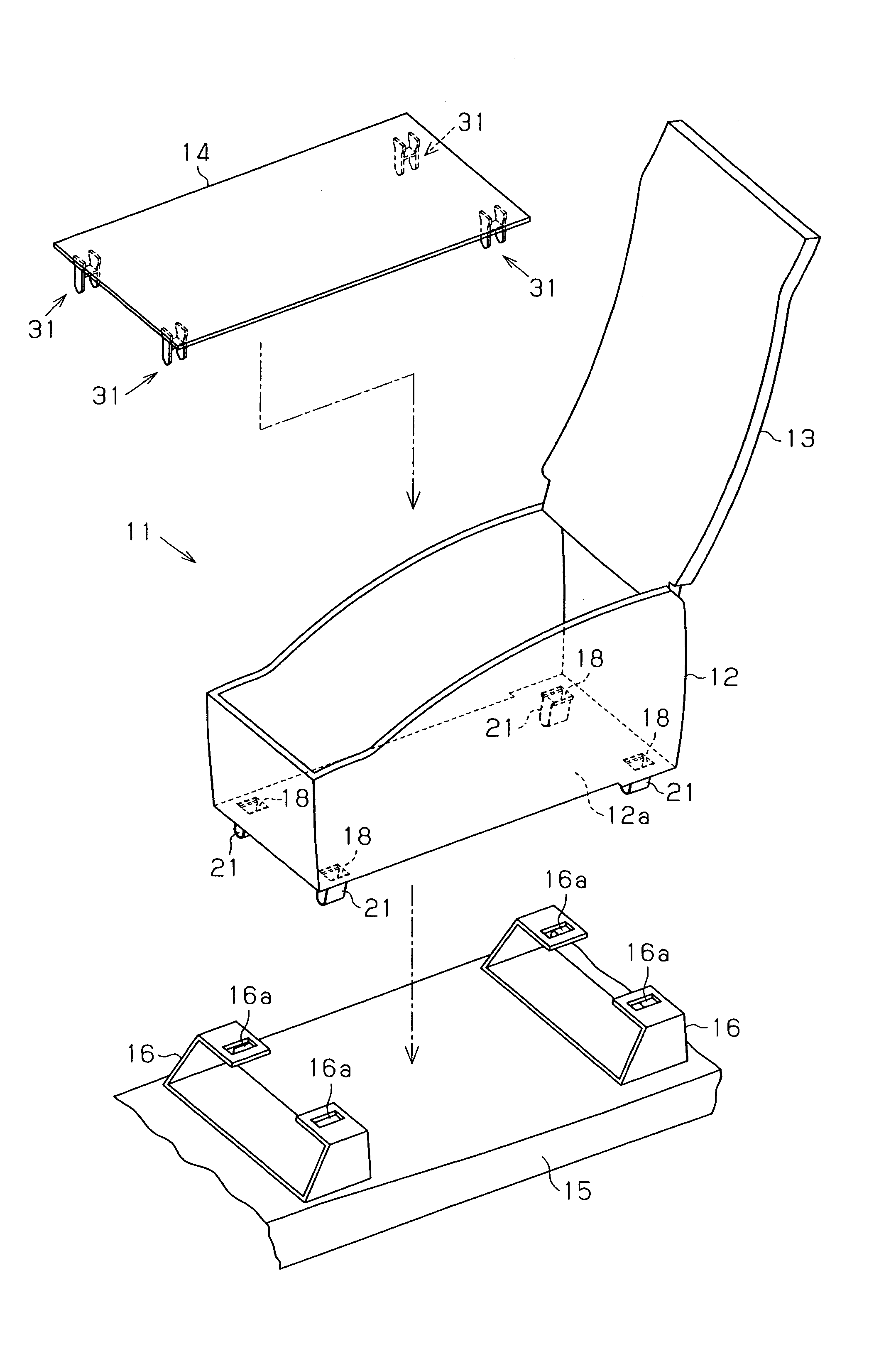
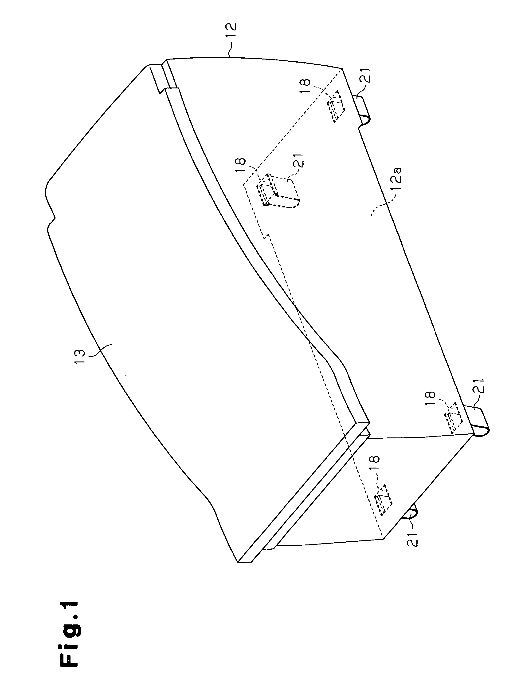
[0024]As shown in FIGS. 1 and 5, a console 11 includes a rectangular console body 12 having a bottom, a lid 13, a bottom cover 14 placed on a bottom wall 12a of the console body 12. The console 11 is located between the driver's seat and the front passenger seat in a passenger compartment of a vehicle. The longitudinal direction of the console 11 coincides with the front-to-rear direction of the vehicle. A pair of front and rear brackets 16 are fixed to a floor panel 15 forming the floor of the vehicle. The console 11 is attached to the brackets 16. The brackets 16 can be regarded as components that form part of the floor panel 15.

[0025]As shown in FIG. 3, the brackets 16 are located at a position corresponding to a front portion of the console body 12 (front position with respect to the front-to-rear direction of the vehicle) and a position corresponding to a rear portion of the conso...


PUM


Abstract

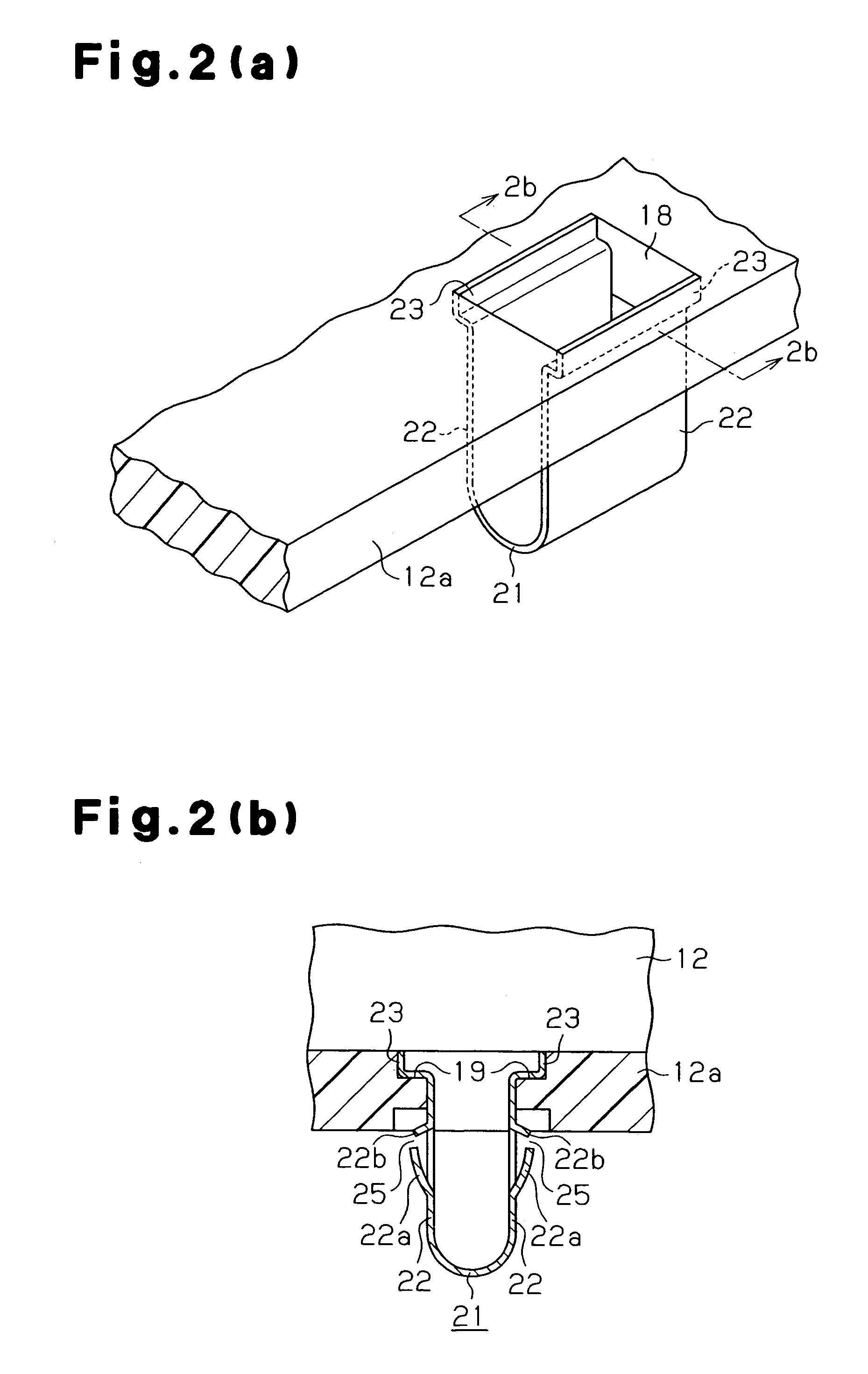
A console is attached to brackets fixed to a floor panel of a vehicle. Each bracket has a pair of fitting holes. The console includes a console body having a rectangular bottom wall. An insertion hole is formed in each of the four corners of the bottom wall. Each insertion hole corresponds to one of the fitting holes. Clips are provided at portions of the bottom wall, each portion corresponding to one of the insertion holes. Each clip has two fitting portions that are arranged to face each other. When each clip is inserted into the corresponding fitting hole, the fitting portions are fitted to an inner wall of the fitting hole so that the console body is attached to the brackets. With the clips inserted into the fitting holes, a fastening member having two legs is inserted into each insertion hole so that the legs are located between the corresponding fitting portions to prevent the clip from being removed from the fitting hole.

Description

BACKGROUND OF THE INVENTION[0001]The present invention relates to a mounting structure for a console located between the driver's seat and the front passenger seat in a vehicle such as an automobile.[0002]Conventionally, a console is installed in a vehicle by using screws. However, installment with screws involves troublesome steps in which a worker has to get on and off a vehicle a number of times in an automobile assembly line. In this respect, for example, Japanese Laid-Open Patent Publication No. 8-11635 discloses a console that facilitates the assembly. The console of the publication includes a body. A rib projects downward from an inner surface of an upper wall of the body. A fixing clip is attached to the rib. On the other hand, a bracket is fixed to a floor tunnel to which the console is to be attached. The bracket has a slit. The fixing clip of the body is engaged with the slit so that the console is installed on the floor tunnel. This console does not require screws to ins...

Claims


Application Information

Patent Timeline
Patent Type & Authority Patents(United States)
IPC IPC(8): B60R7/04B60N3/12
CPCB60R7/04
Inventor SAKAKIBARA, YASUHIROIKUTA, HIROTOTANAKA, AKIRA
Owner TOYODA GOSEI CO LTD
Learn More